Content last revised on October 11, 2026
G121STN02-0 Service and Integration Checklist
- Confirm the installed display identification as G121STN02-0 and record the original cable orientation before removal.
- Inspect the panel frame, gasket contact area, connector shell, and rear clearance for mechanical stress or contamination.
- Compare the host controller’s display interface, backlight control, and power sequencing with the original equipment documentation.
- Run a cold start and warm restart test before releasing the instrument for service.
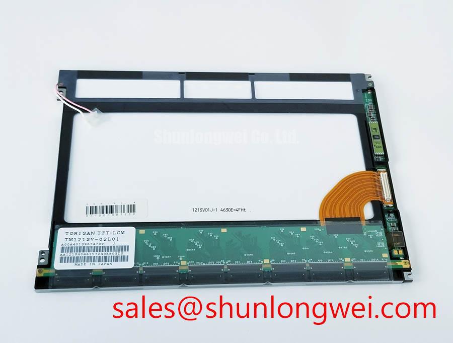
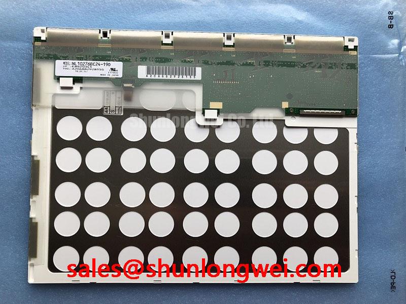
The G121STN02-0 is an AUO industrial-grade LCD/HMI panel identified as a TFT-LCD active matrix color display module in a standard form factor. For precision electronic test and measurement instruments, replacement work should begin with interface preservation rather than forced mechanical fitting. Cable position, frame seating, optical surface condition, and the controller’s startup sequence all influence whether the replacement behaves correctly in the finished instrument.
| Manufacturer | AUO |
| Model | G121STN02-0 |
| Product category | Industrial Grade LCD/HMI Panel |
| Display construction | TFT-LCD Active Matrix Color Display Module |
| Specification status | Decoded Baseline / Standard Form Factor |
Shielded FFC/FPC Flat Flexible Cable Grounding across 360-Degree Connector Shells
Pixel jitter and horizontal noise bands near variable-frequency motor equipment should first be treated as a cabling and return-path problem. The panel itself does not establish system-level EMC performance. The host design determines how the flexible cable shield, connector shell, signal reference, and chassis bonding interact.
A 360-degree shield termination is a useful Design Consideration when the equipment enclosure is exposed to strong common-mode fields. The shield should make broad, low-inductance contact with the connector shell rather than relying on a long drain wire. The cabinet bonding strategy must also prevent shield current from being routed through sensitive display reference conductors.
For differential display links, the system integrator should compare the controller’s specified pair impedance and skew allowance with the actual cable and PCB layout. A commonly used high-speed design target is 100 Ω ±10% differential impedance with closely matched pair lengths, but this is a host-interface engineering target, not an AUO factory specification for this model. The permitted skew must come from the controller and cable documentation; if the design uses a 50 ps budget, the complete path should be measured rather than assumed.
When intermittent noise appears only while a motor drive is switching, compare the display signal with the drive disabled and enabled. Check whether the disturbance follows the cable route, connector shell, or supply return. A common-mode ferrite may be evaluated as a system-level suppression component, but its impedance profile, saturation behavior, and placement must be selected against the actual noise spectrum.
For a same-size service comparison, engineers may review G121SN01 V402 as a separate compatible display option. Compatibility still depends on the controller protocol, mounting geometry, optical requirements, and cable arrangement.
Single Vertical Hairline Defect & Sub-Pixel Column Driver Open-Circuit Localization
A single vertical line requires controlled image testing before any mechanical intervention. Display the primary red, green, blue, black, and white screens from the instrument’s test utility, then observe whether the line remains fixed in the same column across every color. A line that changes character with image content should be evaluated differently from a line that remains sharply continuous.
Use a flashlight at approximately 45 degrees to inspect the dark display surface with the panel operating at low ambient illumination. This can help separate a surface or backlight irregularity from a column-driver-related line defect, but it cannot by itself identify the failed internal element. Avoid pressing the active area or flex-bond region because local force can change the appearance of a marginal connection and complicate the diagnosis.
COG driver micro-fracture is a possible service hypothesis when a hairline defect changes with temperature or chassis movement. It should remain a diagnostic hypothesis until the panel has been compared with a known-good signal path and inspected under controlled conditions. A backlight fault generally changes illumination across a region, while a column-related defect follows image data at a consistent position; the distinction is best confirmed by repeating the color sequence and observing the panel at different brightness levels.
Cold operation can lengthen liquid-crystal response because viscosity changes with temperature. If a precision test instrument is expected to start below room temperature, the enclosure designer may evaluate a controlled warm-up strategy and verify grayscale transitions during the actual cold-start sequence. The display controller’s timing, refresh behavior, and image update method must be assessed together with the panel rather than adjusted from visual impressions alone.
High-Humidity Storage Margins (60°C / 90% RH) & Delamination Prevention Protocols
Humidity exposure should be managed through enclosure sealing, storage control, and condensation prevention rather than by assuming that every industrial LCD has the same environmental rating. The listed product identity establishes the panel category and form factor, but storage and operating limits must be taken from the applicable technical documentation for the exact supply and revision.
Before installation, inspect the bezel perimeter and gasket contact surface for dust, compression loss, or uneven seating. A gasket that is locally lifted can create an optical leak path and allow moisture or contaminants to reach the display cavity. Mechanical fasteners should distribute load evenly across the frame; excessive local force can produce visible pressure marks, uneven luminance, or Mura-like patterns after assembly.
Thermal cycling from sub-zero conditions toward a warm, humid environment creates a condensation risk whenever the panel surface is colder than the surrounding air’s dew point. A practical Design Consideration is to control the enclosure warm-up path and prevent immediate exposure to humid air after cold storage. The service team should allow the equipment to stabilize before applying power or wiping the optical surface.
High-illumination inspection also needs a defined optical reference. Sunlight, overhead luminaires, and instrument-room reflections can make contrast appear unstable even when the display signal is unchanged. Anti-glare or anti-reflective treatment should be evaluated as part of the complete front-surface assembly; do not assume that a replacement panel has the same coating, haze, or viewing behavior as a removed unit.
Additional enclosure and installation guidance is available in the Industrial Display & HMI Solutions engineering resource. ⚠️ Maintenance Note: Inspect the cabinet airflow path and perimeter gasket condition during scheduled service so heat and moisture are not allowed to accumulate around the display assembly.
Dynamic Contrast Ratio Stabilization & Liquid Crystal Birefringence Temperature Tracking
Contrast changes with temperature, viewing direction, ambient reflection, and image content, so dynamic evaluation should use the same test pattern and viewing position used by the original instrument. The G121STN02-0 should not be described as an IPS or MVA panel without an applicable manufacturer specification. Viewing-angle behavior is a panel characteristic that must be compared from the original equipment display, not inferred from the product category alone.
TN-type grayscale inversion, if observed in a particular display technology, can become more noticeable at oblique viewing angles or during cold operation. The correct service response is to document the viewing position, temperature, image pattern, and brightness setting. The viewing-angle characteristics of LCDs explain why contrast and grayscale perception can vary without indicating an immediate electrical failure.
For optical benchmarking, engineers can consult Winstar industrial TFT-LCD and OLED display references to compare general display terminology and measurement practices. Such industry references do not replace the AUO documentation for this specific model.
Backlight behavior should be checked independently from the LCD image path. If the screen data remains correct while illumination fluctuates, inspect the host backlight driver, current regulation, enable timing, open-load response, short-circuit response, and transient handling. PWM dimming frequency, low-flicker performance, and any claimed service-life curve belong to the complete backlight and driver assembly; they should not be assigned to the G121STN02-0 without a matching specification.
For a related display topology review, the NL6448BC20-08E can be examined as a separate display-system reference. Final integration remains dependent on the instrument controller, cable pinout, backlight electronics, mechanical opening, and environmental control.