

Content last revised on September 23, 2026
NEC NL6448BC20-08E Replacement Verification
Measure the logic rail at the panel connector before removing the existing display, then compare the reading with the 3.3 V or 5.0 V ±0.5 V official supply specification for the NEC NL6448BC20-08E. A white screen, unstable graphics, or driver latch-up can also result from an incorrect power rail, a loose display cable, or an unsuitable controller configuration, so the supply measurement should be recorded before further troubleshooting.
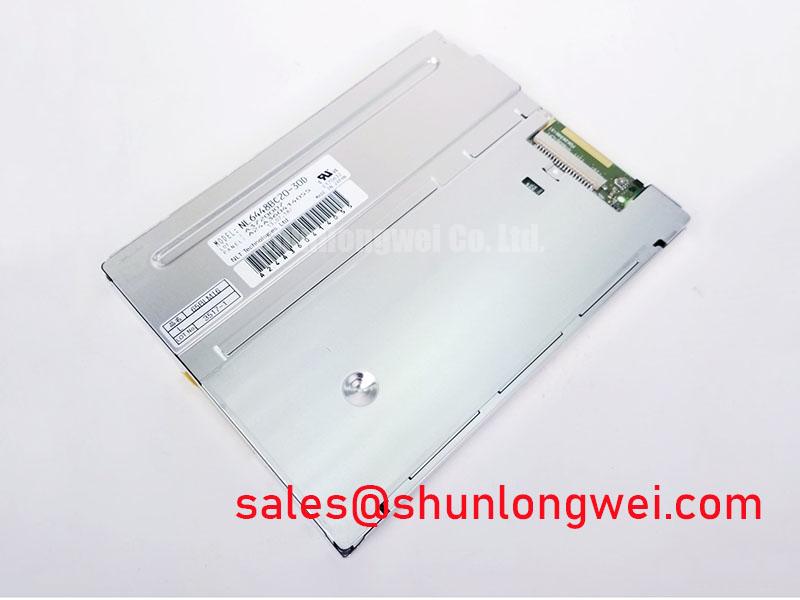
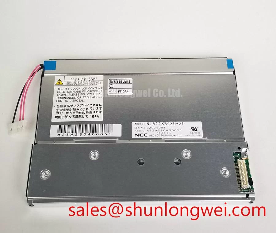
The NL6448BC20-08E is an NEC industrial LCD display evaluated for equipment such as CNC operator panels and robot teach pendants. Replacement work should begin with a comparison of the original panel documentation, connector pinout, display timing, mounting geometry, and backlight control arrangement. The system integrator should verify the required supply voltage from the original panel documentation rather than assuming that a compatible connector guarantees electrical compatibility.
| Parameter | Specified or Engineering Value | Verification Method |
|---|---|---|
| Logic supply voltage | 3.3 V or 5.0 V ±0.5 VOfficial Datasheet Specification | Measure directly at the logic power pins with a calibrated digital multimeter |
| Differential line impedance, where applicable | 100 Ω ±10%Design Consideration for a differential signal path | Verify the differential trace or cable path with suitable TDR equipment where applicable |
| Chassis screw torque | 0.35 to 0.45 N·mDesign Consideration for M3 fasteners | Use a calibrated digital torque screwdriver during installation |
| Backlight lifetime | More than 50,000 hours typical, measured to more than 50% of initial brightnessOfficial Datasheet Specification | Assess luminance with an optical photometer during qualification or condition monitoring |
Temperature Evaluation from −30°C to +85°C and Sub-Zero Liquid Crystal Response
For a CNC operator panel or robot teach pendant exposed to a cold workshop, the display should be checked after the enclosure and cable assembly have reached the intended operating temperature. Liquid crystal response can slow at low temperature, so a delayed gray transition, visible trailing, or temporarily uneven image should be evaluated against a warmed reference panel rather than diagnosed from a single cold start. The relevant question is whether the effect remains within the machine interface requirements after thermal stabilization.
The range from −30°C to +85°C should be treated as an application evaluation condition unless the original NEC documentation confirms the exact operating and storage ratings for the installation. Designers should check the complete panel assembly, including the controller, flexible cable, connector locking mechanism, backlight driver, and enclosure ventilation. A display may tolerate a specified temperature range while the surrounding electronics or cable insulation requires a narrower limit.
At low temperature, allow the panel to stabilize before judging gray-scale performance. At elevated temperature, inspect for image non-uniformity, connector movement, and backlight brightness changes after the enclosure has been operating under representative heat loading. The supplied official lifetime value for the backlight is more than 50,000 hours typical to above 50% of initial brightness. This is a typical specification, not a guaranteed field lifetime under every ambient temperature, drive current, duty cycle, or enclosure condition.
When the backlight is suspected, compare the screen in a controlled environment with the machine controller active. A dark display may involve the backlight driver, the logic interface, the panel supply, or the display data path. If the image is faintly visible under an external light source, the diagnostic direction may shift toward illumination or backlight control, but the result should be confirmed through voltage and signal measurements.
Optical bonding, enclosure sealing, and anti-glare performance must be verified from the original equipment construction records. They should not be assumed from the panel model alone. For equipment requiring moisture or dust resistance, the system integrator should validate gasket compression, cable entry sealing, condensation control, and the service procedure for opening the enclosure.
TTL Digital RGB Bus Synchronization and Logic Power Rail Verification
Before connecting the replacement panel, identify the controller output format and compare it with the original panel documentation. The presence of a matching connector does not confirm identical RGB order, pixel clock behavior, enable polarity, or timing. RGB bit mapping should be checked against the controller configuration so that color errors, split-screen artifacts, shifted images, or intermittent synchronization are not mistaken for a defective LCD cell.
Power sequencing deserves the same attention as the signal mapping. Measure the logic rail during startup and shutdown with an oscilloscope when a multimeter cannot show the transient behavior. Confirm that the controller does not drive data lines while the panel logic supply is outside its permitted range, and verify the reset, display-enable, and backlight-enable relationship from the original system design. The exact rise and fall timing must come from the panel documentation and controller requirements; it should not be inferred from the connector arrangement.
The official logic supply specification is 3.3 V or 5.0 V ±0.5 V. The system integrator should select and verify the correct rail from the original panel documentation, then check the voltage at the panel pins under operating load. Measuring only at the power supply output can miss connector contact resistance, cable drop, or an intermittent locking contact. The related NL192108AC21-01 may be reviewed as a separate display solution when the system architecture requires comparison of controller and backlight arrangements; it should not be treated as an automatic substitute.
For a differential signal link elsewhere in a long cable route, designers should keep the high-speed signal return path continuous and control impedance transitions at connectors and board changes. The supplied engineering benchmark is 100 Ω ±10% differential impedance. This benchmark does not describe the panel’s parallel TTL RGB bus and is not a standalone certification of the complete machine EMC performance. Signal integrity should be checked against the known-good controller and cable assembly using the appropriate probing method.
⚠️ Field Alert: Disconnect power and allow stored energy to discharge before inserting or removing the LCD cable, because live connector handling can expose signal pins to unintended electrical stress.
Chassis M3 Fastener Torque Sizing from 0.35 to 0.45 N·m
Inspect the metal bezel, mounting tabs, threaded inserts, and panel seating surface before fitting the NEC display. The chassis should support the panel evenly without forcing a corner into position. Uneven clamping can create localized optical non-uniformity, edge shadowing, or mechanical stress that changes as the equipment warms and cools.
The supplied 0.35 to 0.45 N·m value is a Design Consideration for M3 chassis fasteners. It should be applied with a calibrated torque tool and confirmed against the machine manufacturer’s mechanical drawings. Tighten progressively in a cross-pattern so that the bezel seats evenly. Do not use torque as a correction for a warped bracket, misplaced spacer, damaged thread, or cable trapped beneath the panel.
After installation, display a white, black, and mid-gray test image and inspect the perimeter from the normal operator position. A 45-degree inspection light can help reveal pressure-related shadows, but the panel should also be checked under its intended backlight level. If the image changes when a fastener is loosened slightly, investigate the mounting interface rather than treating the LCD assembly as an electrical failure.
FPC routing requires a separate mechanical review. Keep the flexible cable within the bend path defined by the original equipment and avoid sharp folds at the connector exit. Repeated door movement, vibration, or an unsecured cable can create intermittent contact that appears as random lines or a disappearing image. The connector lock should be fully seated, and the cable should not be used to pull the panel into alignment.
For installations near inverters, servo drives, or robot motor power wiring, separate noisy power conductors from the display signal path where the machine layout permits. The 100 Ω ±10% differential impedance benchmark applies where a differential link is used and should be considered together with cable construction, return continuity, connector geometry, and grounding. A TDR result on a short isolated trace does not represent the complete installed path unless the cable and connector transitions are included in the evaluation.
For replacement planning, engineers may compare the same-size or same-resolution context of NL128102BC28-04. Electrical, mechanical, optical, and timing compatibility still require verification before any alternative is placed into service. This comparison is a sourcing reference, not a prescriptive substitution.
Micro-Twist Mechanical Stress Checks on the Glass Substrate and Driver Area
Carry the panel with two hands and support the rigid edges rather than pressing the active viewing area. During installation, align the panel with the bezel before inserting the fasteners. A small twist introduced by a misaligned bracket can place stress into the glass and bonded driver region, producing symptoms that may appear only after the machine enclosure is closed or transported.
A practical bench check begins with three primary-color screens: red, green, and blue, followed by white and black images. Observe the display directly, then use a flashlight at approximately 45 degrees to inspect dark areas and the perimeter. This can help distinguish an illumination problem from a localized display-line or driver-area defect, but it does not identify a single root cause by itself. Confirm the finding by comparing the logic rail, display data activity, backlight behavior, and cable seating.
If a dark shadow changes when the enclosure is flexed, when a connector is touched, or when a mounting screw is adjusted, stop mechanical manipulation and inspect the mounting stress path. Do not press the glass to test for an intermittent fault. Record whether the symptom follows the panel, the cable, or the controller before authorizing a replacement.
For factory environments with strong electromagnetic noise, verify the differential signal path against a known-good assembly where the system uses such a link. The supplied 100 Ω ±10% impedance benchmark can support a design review, while actual acceptance depends on the complete controller, cable, connector, grounding, and enclosure arrangement. The system engineer should validate signal margins with the installed configuration rather than assigning the display a standalone EMC compliance claim.
Long-term static screens on CNC and teach-pendant interfaces should be reviewed at the system level. Use the controller’s screen rotation, dimming, or idle behavior where available, and verify that any luminance management does not interfere with operator safety messages. Image retention, backlight aging, and thermal conditions should be assessed using the actual interface duty cycle; no field failure rate or fixed service-life prediction should be assigned without qualified test data.
For a broader explanation of panel interfaces, selection factors, and industrial LCD integration principles, engineers can consult The Ultimate Guide to Industrial TFT LCD Technology. The final installation decision should remain tied to the original NEC documentation, measured electrical behavior, the machine’s mechanical drawings, and controlled bench verification.