

Content last revised on September 24, 2026
LTD121C30S Inspection and Documentation
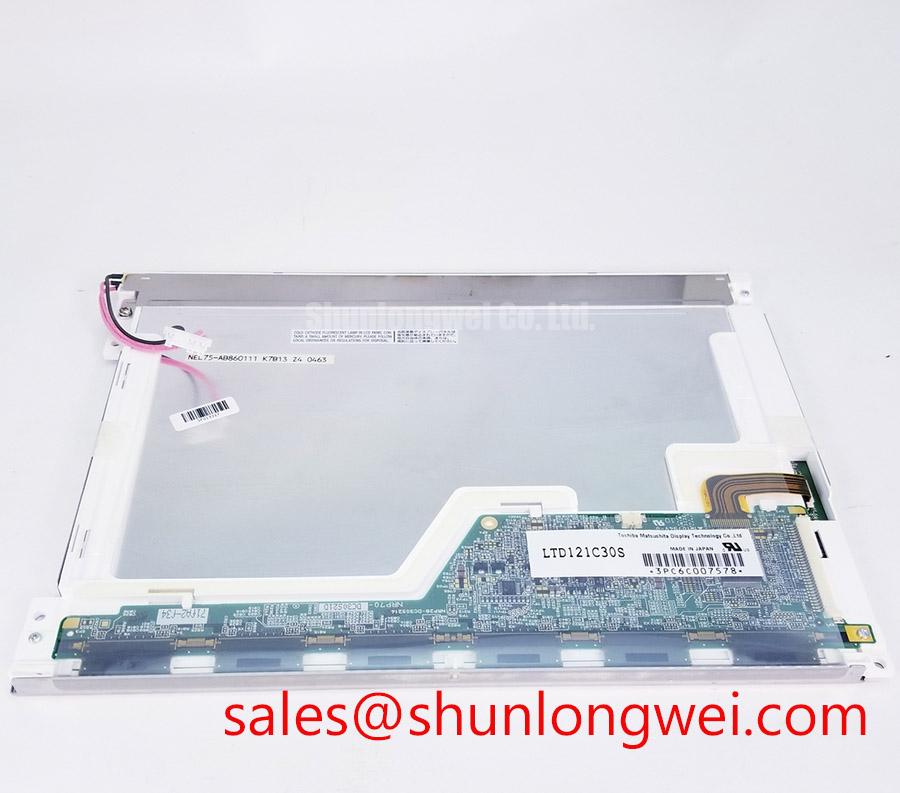
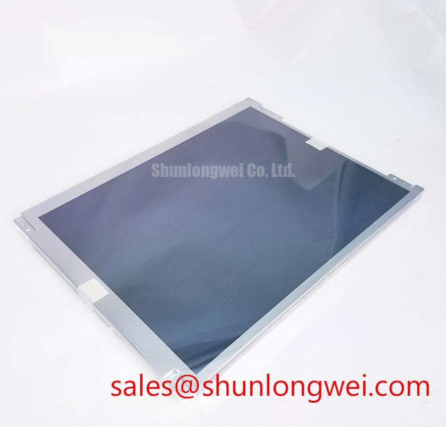
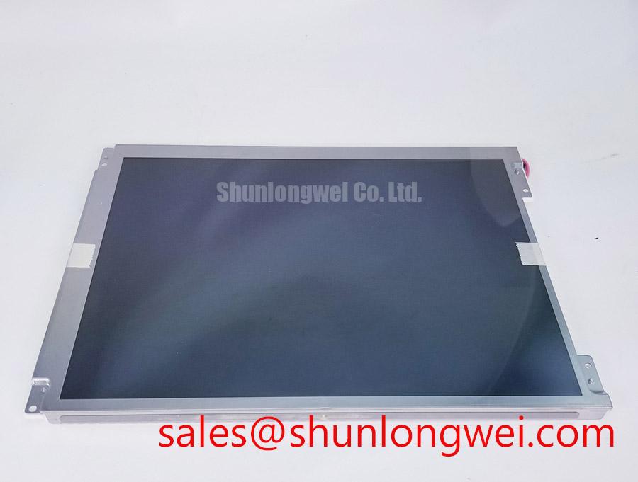
Before connecting the LTD121C30S, inspect the display connector, cable latch, bezel seating, and rear housing for stress or contamination, then verify the original equipment panel documentation before applying power. The official factory identity is a Toshiba / Samsung Industrial Grade TFT-LCD Display Module; the available verified specification confirms the product category and module format, while electrical supply, signal format, backlight architecture, resolution, and mechanical dimensions must be confirmed against the host equipment documentation.
| Official Factory Specification | Verified Information |
|---|---|
| Model | LTD121C30S |
| Manufacturer | Toshiba / Samsung |
| Product Category | Industrial Grade LCD/HMI Panel |
| Module Format | TFT-LCD Display Module |
| Specification Status | Official Factory Spec Verified |
High-Voltage Striking Potential (1500–1650 Vrms) & Secondary Coil Insulation Testing
Start any repair evaluation by identifying the backlight system fitted in the original display assembly rather than assuming that the LTD121C30S uses a particular lighting technology. Some legacy industrial display platforms use high-voltage lamp inverters, while later service assemblies can employ regulated LED backlight arrangements. These architectures require different checks at the driver output, cable interface, enable path, brightness-control input, and power sequencing stage.
A high-voltage ignition figure such as 1500–1650 Vrms must never be treated as an official rating of the LTD121C30S unless it is stated in the original panel documentation. It is a system-level test condition that can be relevant when examining a cold-cathode backlight inverter. Check the inverter secondary wiring, insulation condition, connector retention, and whether the output is balanced between channels. Audible noise, unstable brightness, or intermittent illumination can arise from several parts of the display power chain, so waveform comparison with a known-good assembly is more reliable than assigning a single cause.
For LED-based maintenance designs, constant-current control and PWM dimming behavior should be assessed at the driver board level. Backlight aging, dimming instability, and thermal loading are system-dependent characteristics; no operating-life claim should be attached to this panel without a manufacturer-supported backlight specification. The system integrator should verify the required supply voltage from the original panel documentation before attaching a substitute driver or test source.
🔧 Bench Diagnostic: Disconnect and discharge the equipment power supply before unplugging display or backlight cables, because stored energy in the associated driver circuitry can damage connectors or test equipment.
Diffuser Film & Prism Sheet Thermal Buckling Prevention under Continuous Full-Duty Operation
Continuous full-brightness operation should be evaluated through the complete display enclosure, not by treating the TFT module as an isolated heat source. Inspect whether the rear cover, mounting frame, cable routing, and adjacent electronics obstruct heat dissipation around the display perimeter. Localized hot zones near the backlight driver, power board, or tightly clamped enclosure can influence brightness uniformity and apparent contrast over time.
Design Consideration: Use the equipment enclosure and mounting rails to spread heat away from the display edge where the host design permits it. The final thermal arrangement should be validated with the actual backlight duty cycle, ambient exposure, installed bezel pressure, and airflow conditions. A module placed behind a sealed operator console will behave differently from the same module tested on an open bench.
Claims involving optical film composition, PMMA yellowing resistance, anti-glare coating properties, contrast at a stated lux level, LED L70 behavior, or a 50,000-hour brightness target are not official specifications for the LTD121C30S from the supplied verified information. For outdoor-facing HMI equipment, engineers should measure readability under the intended ambient light condition and compare it with the original display assembly. This is especially relevant when a telematics display is mounted in heavy earthmoving equipment where windshield angle, cab shading, and enclosure depth can change perceived readability.
Where a replacement review is required, LQ10D321 can be evaluated as an interface-comparison candidate. A replacement decision should require confirmation of active area, outline, mounting points, connector position, signal mapping, timing, and backlight requirements before installation.
Normally White TN Grayscale Inversion Mitigation & Optimal Viewing Direction Alignment
Check the original panel’s intended viewing direction before changing the display module or reworking its mounting orientation. A display can appear acceptable at a bench angle yet show grayscale shift, reduced contrast, or color imbalance when observed from the normal seated position in the finished equipment. The LTD121C30S should therefore be evaluated in the physical orientation used by the host HMI, with the operator’s usual eye line and bezel opening taken into account.
Panel technology, viewing cone, surface treatment, and grayscale behavior must not be inferred from the model name alone. IPS, MVA, TN, anti-glare etching, and symmetric viewing-angle claims require direct manufacturer documentation. For repair work, compare a stable test image across the original and candidate panel using grayscale ramps, solid fields, and text edges. This exposes orientation-sensitive changes without presenting unverified optical characteristics as factory data.
Signal integrity is equally important. Whether the host uses TTL or LVDS must be verified from the original controller and panel documentation. JEIDA and VESA mapping differences can produce incorrect colors even when the connector appears mechanically compatible. 💡 Pro Tip: Keep differential data pairs length-matched and routed as controlled pairs to reduce pixel-clock jitter and intermittent image artifacts.
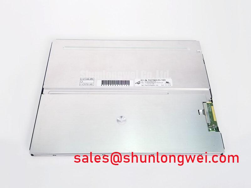
When reviewing another industrial display solution, NL10276BC30-18 may be useful as a separate reference point for assessing broader display-interface and power-integration requirements, subject to full compatibility verification.
Radiated Emissions Compliance (CISPR Class A/B) via Backplate Multi-Point Star Grounding
Horizontal noise bands, pixel disturbance, and intermittent image flicker near variable-frequency motor drives should be investigated as installation-level electromagnetic issues. The LTD121C30S itself must not be represented as independently compliant with CISPR Class A or Class B requirements, because those standards apply to the completed equipment and its tested configuration. Cable shielding, chassis bonding, supply filtering, controller layout, and enclosure construction all influence the final result.
Engineering Recommendation: Maintain a continuous shield termination strategy where the host cable and enclosure design support it, while avoiding unnecessary signal-return discontinuities. The system engineer should assess grounding points, cable exits, ferrite placement, and controller-board reference paths through conducted and radiated testing in the final equipment configuration. A shield connection that improves motor-drive noise immunity in one enclosure can create an unwanted return path in another.
For LVDS implementations, the commonly used differential impedance target of 100 Ω ± 10% is a general interface design consideration, not an official specification of this panel. Confirm the required signal standard, timing relationships, and transmitter output settings with the original system documentation, then verify image stability during nearby motor, relay, and power-conversion operation.
For broader integration and maintenance guidance on industrial TFT panel selection, optical evaluation, interface verification, and environmental testing methods, consult The Ultimate Guide to Industrial TFT LCD Technology.