Content last revised on September 10, 2026
NEC NL10276BC30-18 Inspection and Key Specifications
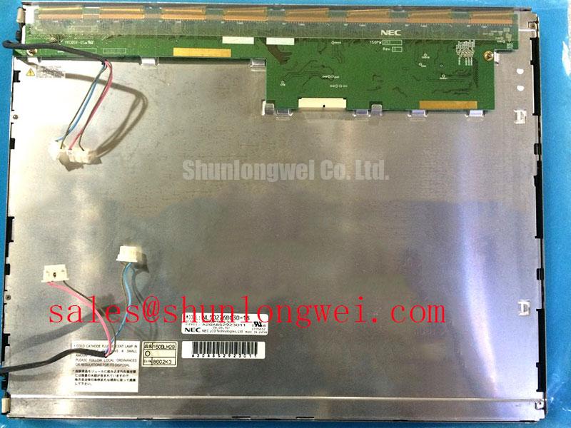
With the equipment de-energized, inspect the 20 pin LVDS connector, its cable latch, and the panel perimeter before connecting the NEC NL10276BC30-18 to a known-good controller. This 15.0 inch industrial TFT LCD has a 1024(RGB) × 768 XGA active format, so a loose differential pair, incorrect pixel mapping, or an incompatible timing board can produce a blank image, color distortion, or split image even when the panel itself is functional.
The official display configuration is a-Si TFT-LCD, TN, Normally White, with 500 cd/m² typical luminance, a 500:1 typical contrast ratio, and typical viewing angles of 80° left, 80° right, 60° up, and 80° down at CR≥10. Its official operating range is −10°C to +70°C, while storage is specified at −20°C to +80°C. The enclosure envelope measures 326.5 mm wide × 253.5 mm high × 17.0 mm deep, which should be checked against the original HMI mounting frame before replacement work begins.
| Official Specification | NL10276BC30-18 |
|---|---|
| Manufacturer | NEC |
| Screen Size | 15.0 inches |
| Resolution | 1024(RGB) × 768, XGA |
| Display Technology | a-Si TFT-LCD, TN, Normally White |
| Luminance | 500 cd/m² typical |
| Contrast Ratio | 500:1 typical |
| Viewing Angle | 80°/80°/60°/80° typical, CR≥10 |
| Signal Interface | 1 channel, 8-bit LVDS, 20 pins |
| Operating Temperature | −10°C to +70°C |
| Storage Temperature | −20°C to +80°C |
| Outline Dimensions | 326.5 × 253.5 × 17.0 mm |
VESA vs. JEIDA Data Mapping Alignment & Even/Odd Channel Signal Integrity
The NL10276BC30-18 uses a one channel, 8-bit LVDS interface with 20 pins as an Official Specification. That identifies the signal class and connector population, but it does not independently confirm the host logic supply requirement, pin-by-pin assignment, LVDS mapping convention, or permitted power sequencing for a particular controller assembly. The system integrator should verify the required supply voltage, connector pinout, data mapping, and timing sequence from the original panel documentation and the host display board documentation before applying power.
VESA and JEIDA mapping differences can make a valid LVDS waveform appear as incorrect color depth, unusual color ordering, banding, or a divided image. These symptoms should not be treated as proof of panel damage. A practical service sequence is to compare the original cable orientation, inspect each connector contact for displacement, confirm the controller output standard, and test with a known-compatible display path where available. If an oscilloscope and appropriate differential probing are available, engineers can compare the affected signal path with a known-good machine rather than relying on visual symptoms alone.
Design Consideration: LVDS routing should preserve controlled differential behavior and avoid unnecessary cable stress, sharp bends, or unrestrained movement near the connector. This is especially relevant in vibrating industrial consoles, where a panel cable can look seated while its latch has not fully engaged. The panel’s 500:1 typical contrast ratio and 500 cd/m² typical luminance describe its specified optical performance; they do not establish sunlight readability at a particular ambient light level, nor do they confirm an anti-glare surface treatment. Direct-sunlight suitability depends on the finished enclosure, viewing geometry, cover window, and system-level optical design.
For a same-format comparison during repair planning, the NL10276BC16-06 can be reviewed as a separate panel option. Mechanical dimensions, connector placement, pinout, optical characteristics, and controller compatibility still require independent confirmation. Matching a nominal screen size and XGA resolution alone does not establish interchangeability.
Optical Luminance Degradation Curve & CCFL-to-LED Modernization Retrofit Pathways
The official information for the NL10276BC30-18 identifies the panel’s 500 cd/m² typical luminance, but it does not establish the installed backlight type, inverter requirements, backlight input characteristics, dimming method, acoustic behavior, or a rated brightness-life curve. Service personnel should therefore identify the original backlight supply architecture from the host equipment documentation before diagnosing a dim screen or planning a retrofit.
A visibly dark screen can originate in several places: a reduced backlight output, missing enable control, incorrect dimming command, a power-stage protection response, optical contamination in the surrounding assembly, or a loss of image data that is only noticed under strong illumination. The useful first task is to separate panel-image activity from illumination activity. Check the original harness condition, relevant power rails at the host board, enable behavior, and the display image under controlled lighting. Do not connect an assumed LED driver or a high-voltage lighting supply to the panel without documented compatibility.
Engineering Recommendation: a backlight modernization project should be treated as a system redesign rather than a drop-in display adjustment. The mechanical stack, heat path, electrical isolation, dimming control, optical uniformity, and control-board behavior all need verification in the actual equipment. Claims concerning LED half-life, brightness retention, or operating-hour life require a documented source and test conditions; no such life value is stated here as an Official Specification for this panel.
Optical bonding may be evaluated at enclosure level where a machine builder needs to reduce internal reflections, dust ingress pathways, or moisture exposure between an external protective window and the display surface. It is not an identified factory feature of the NL10276BC30-18. Any bonded assembly must be validated for serviceability, thermal expansion, edge loading, and the required display appearance under the target ambient conditions.
For equipment with static HMI screens, avoid assuming that persistent image traces are caused by a single display fault. Long-duration fixed graphics, controller behavior, operating temperature, and the specific LCD characteristics can all influence what an operator sees. A controlled comparison using alternate screen content and normal operating conditions gives more useful evidence than immediate replacement.
Preventing Frame Lag & Image Smearing in Cryogenic Storage & Outdoor Industrial Facilities
The NL10276BC30-18 is officially rated for operation from −10°C to +70°C. A unit stored at a lower temperature may remain within its separate −20°C to +80°C storage range, but storage capability is not the same as powered display performance. Before energizing a panel that has been kept in a cold area, allow the complete display assembly and its host electronics to stabilize under the equipment’s intended operating conditions.
At low ambient temperature, liquid-crystal response can slow and motion can appear less crisp. That observation does not, by itself, diagnose a failed panel. The controller frame rate, image source, cable integrity, interface timing, and ambient temperature should be examined together. When a display is installed in an outdoor machine enclosure or a cold storage interface, designers should verify the actual panel temperature, the enclosure’s heat transfer, and the resulting image response during representative duty cycles.
Heater strips, thermal insulation, and temperature-managed enclosures are system-level measures that may be considered where the equipment must present critical information below the panel’s specified operating range. Their electrical control, placement, condensation behavior, and thermal limits are determined by the machine design and require validation against the original panel documentation. They are not factory characteristics confirmed for the NL10276BC30-18.
Mechanical restraint deserves equal attention. The 326.5 mm × 253.5 mm × 17.0 mm outline must sit flat in the mounting structure without twisting the display frame or forcing the LVDS cable into a tight bend. In mobile industrial equipment, vibration isolation belongs to the complete HMI assembly, including the bezel, fasteners, cable retention, controller board, and protective cover. Do not infer shock or vibration qualification from the listed temperature and dimensional specifications.
Design Consideration: leave sufficient strain relief for the display harness so normal equipment movement is not transmitted directly into the connector. Cable routing should be checked after the bezel is fully installed, because a cable that passes inspection before final assembly can become pinched when the enclosure closes.
Flashlight Dark-Shadow Optical Diagnostic to Isolate Logic vs. Backlight Failure Modes
When a machine terminal appears black, begin with a controlled flashlight inspection rather than immediately changing the panel. With the display powered through its documented system path, aim a flashlight across the screen at an oblique angle and look for faint menus, cursor movement, or recognizable image areas. A faint image may indicate that image data is present while the illumination path needs investigation. No faint image does not prove a panel failure; it may also reflect loss of LVDS data, incorrect timing, absent panel power, controller reset behavior, or a system interlock condition.
Continue with a simple primary-color test pattern from the known-good controller when the host equipment permits it. Display red, green, blue, white, and black fields in sequence, observing the full active area for abnormal lines, color imbalance, intermittent sections, or image changes when the cable is gently supported. This does not assign one defect to one cause. It helps separate persistent panel-area behavior from controller output, cable movement, and lighting issues that can change during the test.
Inspect the LVDS connector under magnification for incomplete seating, foreign material, latch damage, or contact displacement. Check that the cable is routed without tension across the panel edge and that the host-side connector is equally secure. If the image returns when cable pressure changes, treat the observation as a reason for further connector and harness inspection, not as conclusive evidence of an internal display defect.
⚠️ Field Alert: Disconnect system power and confirm stored energy has discharged before inserting or removing the LVDS cable, because live connector handling can disturb signal and supply contacts.
Where the panel shows no image during the flashlight check, compare documented panel supply behavior and LVDS activity with a known-good signal path before deciding whether the issue is in the display, harness, interface board, or machine controller. For broader troubleshooting context covering TFT operating principles, integration concerns, and common assessment mistakes, see The Ultimate Guide to Industrial TFT LCD Technology.