

Content last revised on September 10, 2026
AA104VB04 Mitsubishi Electric TFT LCD Display Module for Industrial HMI
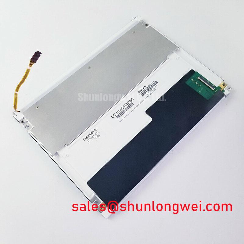
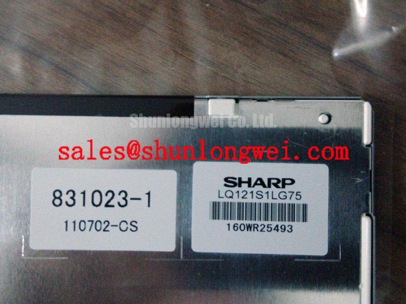
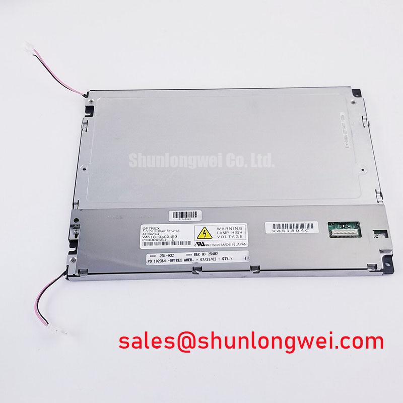
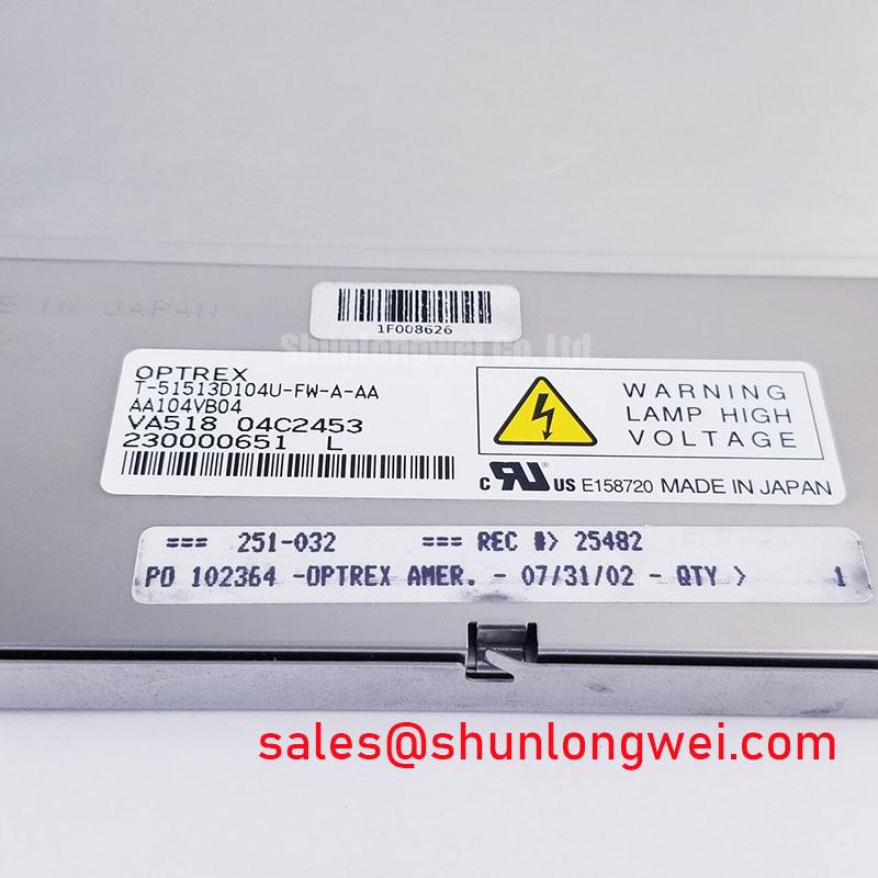
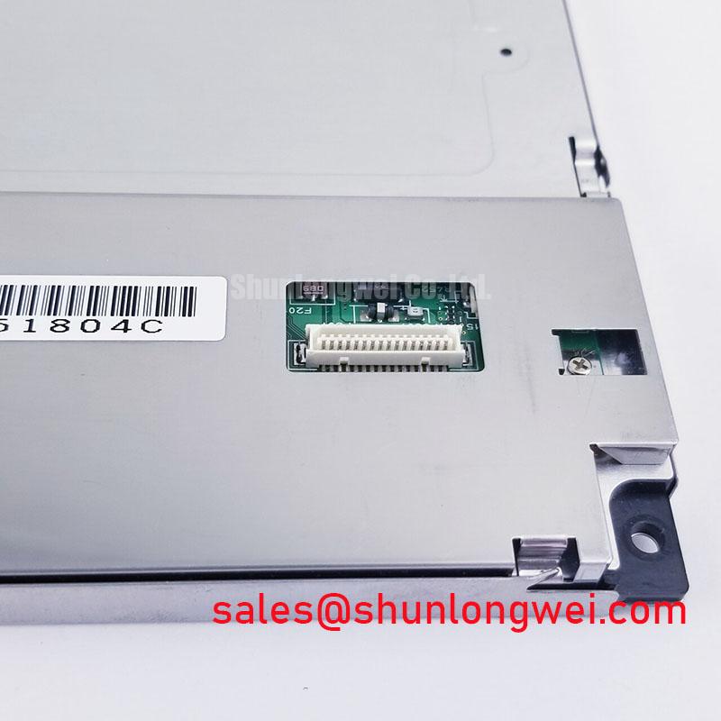
Begin incoming inspection by checking the AA104VB04 label, connector condition, frame integrity, and visible panel surface before applying power. Record the unit identity against the equipment service documentation, then inspect for cracked glass, bent contacts, contamination, uneven frame pressure, and signs of cable misalignment. The supplied factory specification identifies this product as a Mitsubishi Electric Industrial Grade LCD/HMI Panel in a TFT-LCD Display Module package, with an Official Factory Spec Verified status.
This product page separates confirmed product information from system-level integration considerations. The available factory context confirms the model, manufacturer, product category, and module construction, but it does not establish a complete electrical interface definition, display resolution, active-area dimension, brightness rating, viewing-angle specification, backlight technology, supply voltage, or connector pinout. The system integrator should verify those values from the original panel documentation and the equipment service manual before installation.
| Item | Confirmed information |
|---|---|
| Model | AA104VB04 |
| Manufacturer | Mitsubishi Electric |
| Product category | Industrial Grade LCD/HMI Panel |
| Package or housing description | TFT-LCD Display Module |
| Specification status | Official Factory Spec Verified |
| Intended evaluation context | Industrial display and HMI equipment, subject to system compatibility verification |
Single Vertical Hairline Defect and Sub-Pixel Column Driver Open-Circuit Localization
A narrow vertical line should be investigated with the panel connected to a known-good display source and operated through solid red, green, blue, white, black, and mid-grey test fields. This primary-colour sequence helps separate a pixel or sub-pixel response problem from a backlight or image-processing problem. A line that remains fixed in the same physical position while the input image changes deserves closer attention around the panel edge, connector seating, and column-drive region. This observation is diagnostic evidence, not a definitive failure declaration.
Use a low-intensity flashlight at approximately a 45-degree angle with the display showing a dark field. If the apparent line changes with reflected light or becomes visible only because of surface glare, inspect the cover surface and frame pressure before disturbing the electrical connections. If the line remains visible without a corresponding change in reflected light, compare the defect on a dark field, bright field, and uniform grey field. The purpose is to determine whether the symptom follows luminance, colour selection, or image data.
The AA104VB04 factory information supplied for this listing does not provide a pixel defect classification, column-driver failure threshold, COG construction specification, or published backlight life curve. Those details should not be inferred from the model number. An incoming QA record can still be useful when it documents the exact test pattern, warm-up condition, ambient environment, connector state, and location of the observed line. Repeating the same test after reseating the external display cable may help identify an intermittent contact or signal-path issue, provided the equipment is isolated and handled under appropriate ESD controls.
Backlight ageing should be assessed separately from pixel addressing. A dim field with generally uniform image data may point toward the illumination path, optical layers, driver operation, or thermal conditions, while a sharply localised line may require signal and panel-drive investigation. The supplied product data does not confirm an LED or CCFL backlight, a 50,000-hour rating, an MTBF value, or a half-brightness lifetime. Any such value must be taken from the original Mitsubishi Electric documentation applicable to the exact revision.
For dimensional or resolution matching, compare the removed panel’s mechanical drawing, active area, connector position, and electrical interface with the documented AA084VC01 reference. It is a separate model and should be treated only as a neutral same-family comparison point, not as an automatic substitute for AA104VB04.
💡 Bench Tip: Disconnect power before reseating the display cable, keep the flex cable straight at the connector entrance, and close the connector lock evenly without applying pressure to the glass.
Controlled Differential Flex Routing and High-Frequency Jitter Checks
Before connecting AA104VB04 to a controller, identify the actual signal standard from the original equipment documentation. The supplied factory context does not confirm LVDS, TTL, JEIDA, VESA mapping, connector pin assignments, logic supply voltage, power-on timing, or signal polarity. Do not select a controller because its connector appears mechanically similar. The system integrator should verify the complete interface definition, including data mapping, clock arrangement, cable orientation, enable signals, and the required supply voltage.
Where the documented interface uses differential signalling, routing should preserve pair symmetry, avoid unnecessary stubs, and maintain a continuous reference path. The often-used 100-ohm differential target is a Design Consideration for a compatible high-speed interconnect, not a confirmed AA104VB04 factory parameter. The finished assembly should be checked against the controller and cable documentation, with signal quality verified at the receiving end under the actual operating condition.
Jitter and split-screen artefacts should be assessed with a known-good source pattern containing vertical bars, fine text, grey ramps, and alternating data transitions. Observe the clock and data relationship at the panel-side connection where practical. A distorted edge, unstable image boundary, or colour-bit displacement may involve impedance discontinuity, incorrect data mapping, insufficient grounding, connector contact variation, or controller timing. The symptom alone does not identify one root cause.
Power sequencing is also system dependent. The supplied information does not state whether AA104VB04 requires a defined delay between logic supply, display enable, reset, or backlight control. The integrator should reproduce the original equipment sequence and verify rise, fall, enable, and discharge behaviour with an oscilloscope. White-screen startup, residual images, or failure to initialise should be evaluated against the original controller timing rather than corrected by imposing an undocumented voltage or delay.
PWM dimming frequency and duty-cycle linearity cannot be assigned to this model from the supplied factory data. If the equipment includes a separate backlight controller, its operating range must be checked against that controller’s documentation and the panel assembly requirements. Visual flicker, audible noise, or uneven brightness can arise from the driver, cable coupling, thermal distribution, or optical assembly, so the panel should be evaluated as part of the complete display system.
For a related Mitsubishi Electric display solution, engineers may review AA104VC01 as a separate companion reference. Compatibility remains subject to the original equipment schematic, display controller configuration, mechanical envelope, and documented electrical requirements.
Industrial EMI Noise Immunity, Chassis Shielding Continuity and Common-Mode Ferrite Evaluation
When a display is installed near switching power equipment or variable-frequency drives, begin with a cable and grounding survey before changing the panel. Inspect whether the display cable follows noisy power conductors, whether the chassis bond is continuous, and whether the cable shield terminates according to the equipment designer’s grounding scheme. These are Design Considerations for system integration and are not Mitsubishi Electric EMC certification claims for AA104VB04.
The supplied product information does not confirm a shielded FFC or LVDS cable, a required 360-degree shield termination, a ferrite specification, a common-mode impedance value, or immunity performance beside a 400 V motor drive. If horizontal bands, pixel jitter, or intermittent image loss appear only while a nearby load switches, compare the display with the load disabled, then monitor the supply rails and display clock with suitable probing. Maintain the original cable arrangement during comparison because rerouting can change both coupling and reference currents.
A common-mode ferrite may be evaluated by the system engineer when the measured interference is common to both conductors and the added component does not compromise the intended signal waveform. Its suitability depends on the cable construction, operating frequency, current, connector arrangement, and enclosure bonding. It should not be selected solely from a nominal part number or installed as a guaranteed cure for image noise.
Clock jitter and data hold margin must be verified against the actual transmitter, cable, receiver, and temperature range. No TTL or LVDS timing limits are included in the supplied AA104VB04 data. The correct engineering action is to obtain the panel interface specification, measure the signal at the panel-side connector, and compare the observed timing with the documented receiver requirements. A display that passes a static image test may still show errors during high-activity patterns or switching events.
For service work on railway passenger information systems or cab signalling displays, the relevant equipment documentation should also define isolation, bonding, surge protection, and enclosure requirements. AA104VB04 may be evaluated in such applications only after the complete assembly has been checked for mechanical fit, interface compatibility, environmental protection, and system-level EMC performance. The broader Industrial Display and HMI Solutions reference provides a practical context for reviewing those integration questions without assigning unverified ratings to this panel.
Acoustic Capacitor Buzz and EMI Emissions across Display Dimming Operation
Noise heard during display operation should be localised with the panel and backlight controller operating under several brightness settings and image patterns. Listen near the controller, power conversion area, cable entry, and display frame, then compare the result with the backlight disabled where the equipment permits that test. A tonal sound that changes with brightness can involve the external driver or magnetic components, while image noise that changes with data activity can involve signal integrity or grounding. These observations require confirmation through electrical measurement.
The supplied AA104VB04 information does not identify a CCFL inverter, LED driver, cold-ignition voltage, PWM frequency, dimming ratio, acoustic emission limit, or backlight lifetime. The values cited in the requested application outline therefore cannot be presented as specifications of this model. The integrator should verify the original backlight architecture and controller requirements before evaluating ignition behaviour, dimming linearity, audible noise, or thermal performance.
For systems using a high-voltage backlight circuit, service personnel should follow the equipment manufacturer’s discharge and isolation procedure and use instruments rated for the measured circuit. For systems using a constant-current backlight driver, check current regulation, connector contact, cable routing, and heat spreading under the complete enclosure condition. A brightness reduction or local hot area should be documented with the display pattern, ambient condition, driver state, and measurement location rather than assigned to one internal material or optical structure that has not been confirmed.
EMI emission checks belong to the complete display assembly, including the panel, controller, cable, power supply, enclosure, and grounding arrangement. AA104VB04 as an individual display module must not be represented as independently certified to CISPR, EN 55011, railway, or other system-level EMC requirements. Engineers should verify the finished equipment against the standard and test plan applicable to the installation.
Before approving a replacement, compare the original module’s mounting points, viewing orientation, connector clearance, cable bend path, image format, controller mapping, backlight interface, and power sequence with the proposed AA104VB04 unit. The confirmed product identity is Mitsubishi Electric AA104VB04, an industrial-grade TFT-LCD display module; all unlisted electrical and optical values remain system-documentation items for engineering verification.