

Content last revised on September 24, 2026
Mitigating Gray to Gray Response Time Escalation during Cold Start Machine Power Up
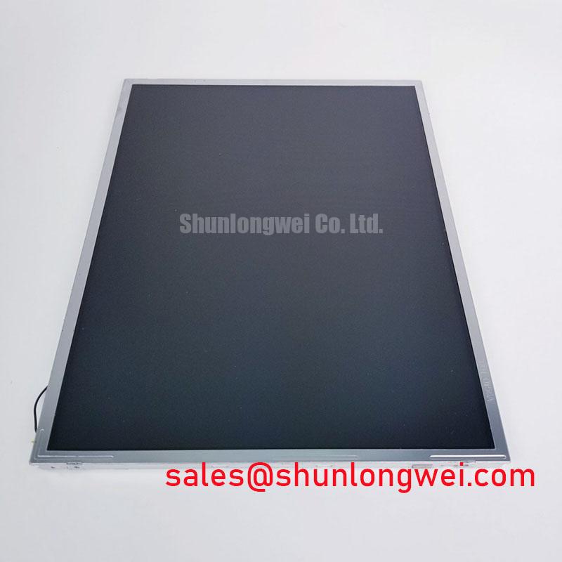
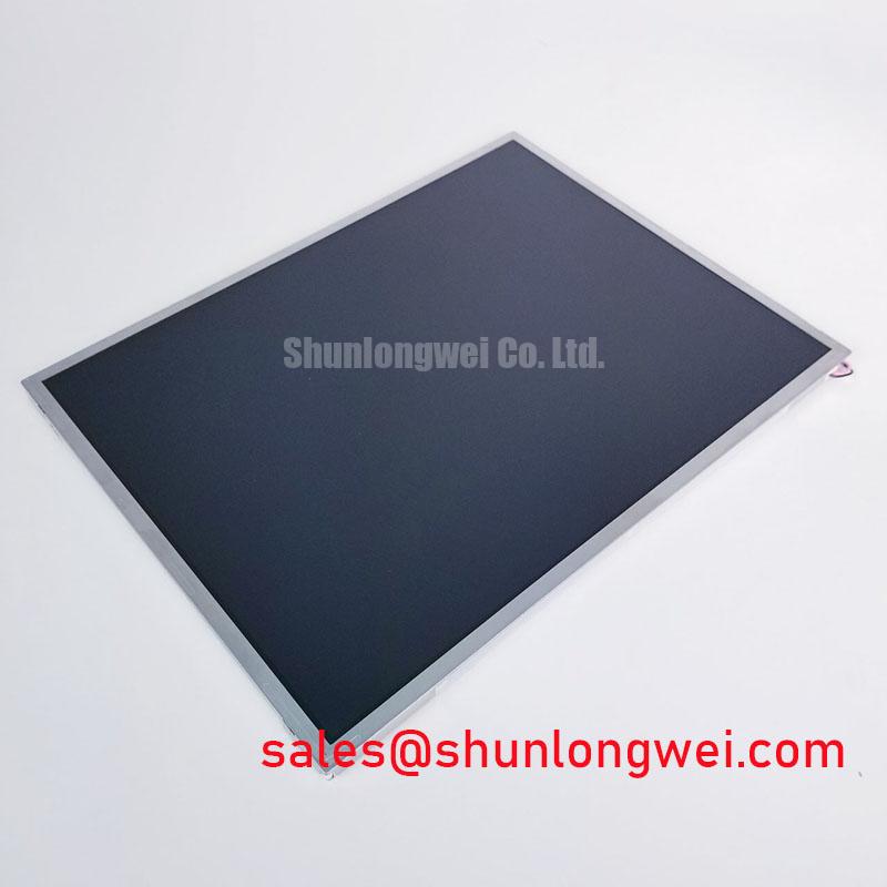
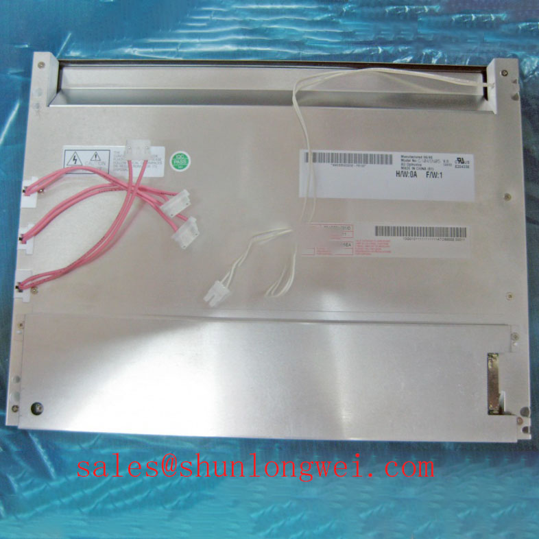
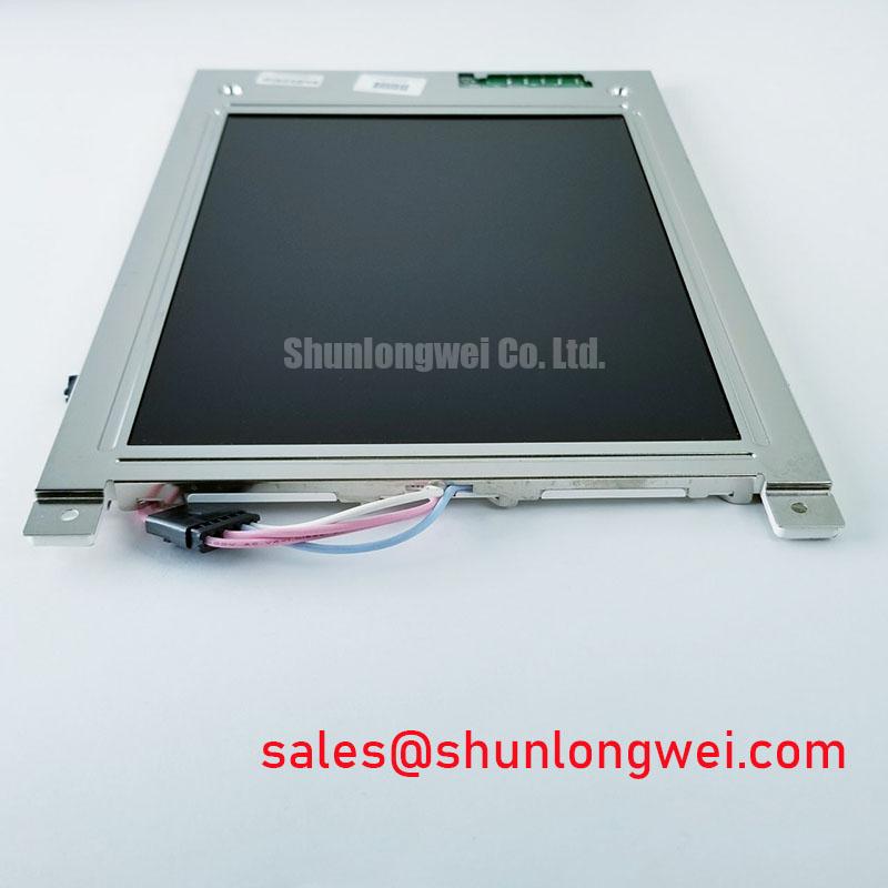
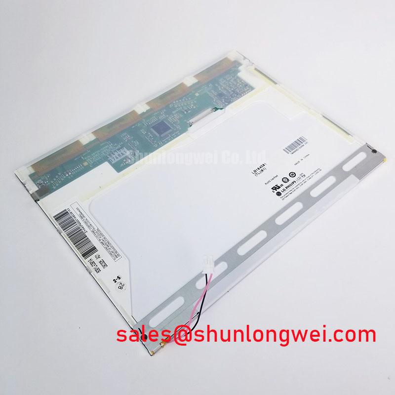
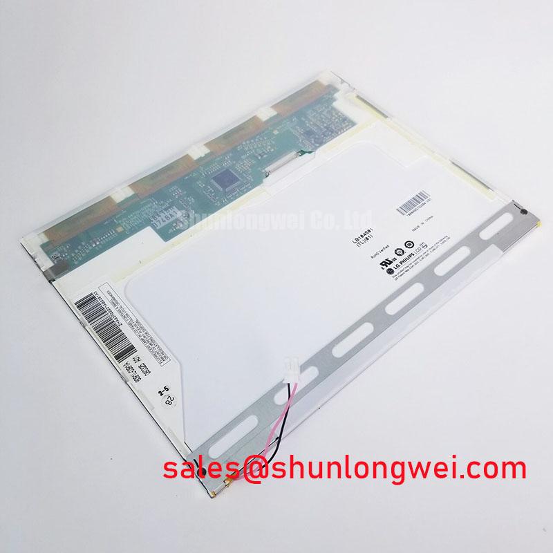
Power down the host equipment, inspect the panel connector and bezel for mechanical stress, then compare the installed label with LB104S01-TD01 before applying power. This unit is identified in the supplied factory data as an LG Display TFT LCD Display Module for industrial HMI use, with its specification status recorded as Official Factory Spec Verified. The available product record does not confirm interface mapping, supply voltage, optical dimensions, backlight method, or operating temperature limits, so those values must be checked against the original panel documentation and the equipment service manual.
| Manufacturer | LG Display |
| Model | LB104S01-TD01 |
| Product category | Industrial Grade LCD/HMI Panel |
| Package or housing | TFT LCD Display Module |
| Specification status | Official Factory Spec Verified |
When a heavy mining shovel or earthmoving machine shows a delayed image after cold start, begin by separating panel response behavior from controller timing and power sequencing. Confirm that the host display controller is delivering the expected video clock and data pattern, then observe whether the image delay changes with panel temperature. A slow visual transition alone is not sufficient to identify a panel fault because source timing, signal integrity, backlight startup, and liquid crystal response can all affect the observed result.
The supplied factory information for LB104S01-TD01 does not state a guaranteed gray to gray response time, cold temperature limit, epoxy sealant rating, TTL input specification, LVDS input specification, clock jitter margin, or data hold time. Designers should therefore avoid treating a proposed industrial temperature range such as minus 30 degrees Celsius to plus 85 degrees Celsius as an official rating for this model. Verify the original LG Display documentation before approving operation across thermal cycling conditions.
For field evaluation, compare a known good video pattern with the machine controller output while monitoring the panel supply and display timing at the same test point. If the source uses LVDS, inspect differential pair continuity, connector seating, common mode behavior, and clock stability. If the source uses a parallel RGB interface, verify the data mapping and pixel clock relationship from the original system schematic. The TCG084SVLQAPNN-AN30-S page may be useful as a separate same class display reference, but it should not be treated as a drop in substitute without mechanical, electrical, and firmware validation.
Diffuser Film and Prism Sheet Thermal Buckling Prevention under Continuous Full Duty Operation
Uneven brightness during continuous operation should be checked at the complete assembly level rather than assigned immediately to the LCD cell. Inspect the rear cover, display frame, light source assembly, and any heat spreader contact points for distortion or concentrated pressure. A narrow metal rail or enclosure contact can create a local thermal gradient, while an uneven mounting surface can alter the optical stack position. These are general Design Considerations, not confirmed internal construction details of this model.
The supplied factory data does not confirm whether this specific display uses LED or another backlight arrangement, nor does it publish PWM frequency, duty cycle linearity, diffuser material, prism sheet construction, light guide material, L70 performance, or B50 life data. The system integrator should verify the required backlight drive method from the original panel documentation. If PWM control is present, evaluate flicker, audible artifacts, brightness tracking, and controller compatibility across the intended duty range rather than applying a generic frequency assumption.
Color terminology should also be handled carefully during replacement assessment. Color depth and gamut are separate display characteristics, and the general reference on Color Depth and Color Gamut Standards may help engineers distinguish source data capability from panel optical performance. It does not establish the color specification of LB104S01-TD01.
Preventing Localized Light Guide Plate Compression Warp on Dark Screen Fields
For dark screen mura or localized shadowing, remove the display from the machine only after recording the original screw positions, bezel seating, cable routing, and enclosure contact points. Inspect the perimeter for compression marks and check whether the frame is twisted when placed on a verified flat work surface. Reassembly should preserve the original mechanical stack and should not force the panel into an enclosure opening that is smaller or differently positioned than the approved assembly.
Specific bezel tolerances, light guide plate construction, M3 fastener torque, optical compression limits, and differential pair requirements are not included in the supplied factory parameter set for this model. The values sometimes used in generic display integration guides must not be presented as LG Display specifications. Minimize mechanical stress and unnecessary cable strain, then confirm the result using a uniform dark test field and a known good controller. For harsh equipment environments, the Industrial Display and HMI Solutions reference provides broader integration considerations without replacing the model specific documentation.
Field Alert: Disconnect machine power and allow stored energy to discharge before removing or inserting the display cable, because live connector handling can stress signal and power contacts.
Verifying Digital RGB Bus Synchronization and Logic Power Rail Requirements
Do not assume that the presence of a 24 bit RGB controller confirms compatibility with this panel. The supplied information does not identify the input as TTL or LVDS, and it does not confirm 3.3 volt or 5.0 volt logic operation, power on rise time, JEIDA or VESA mapping, connector pin assignment, or differential impedance. The system integrator should verify the required supply voltage and interface format from the original panel documentation before connecting a replacement.
During troubleshooting, measure the panel supply at the connector while the host starts, then compare the measured sequence with the controller manufacturer’s timing requirements. Check for split screen, incorrect color order, missing columns, or intermittent synchronization while moving the harness only under controlled service conditions. An oscilloscope comparison with a known good signal path can help identify timing or impedance concerns without assigning a single cause to a visible symptom.
Where the display supply is derived from a machine power converter, review the converter, protection, and grounding arrangement as a system. IEC 60146, available through the IEC 60146 Semiconductor Converters Standard, is relevant to converter engineering but does not certify this LCD module or the complete vehicle display assembly. Final EMC, thermal, vibration, and enclosure decisions remain the responsibility of the equipment designer.