



Content last revised on October 3, 2026
Preventing Spurious Faults: Harmonic Current Injection and Line Filter Guidelines for GP2500-SC41-24V
Compare the GP2500-SC41-24V fault screen with the controller’s event record while the connected equipment changes operating state. A warning that appears only during switching activity needs two separate checks: whether the controller recorded a real fault and whether the HMI received stable power and communications at that moment. Photograph the screen, note the event time, and inspect the relevant connections before treating a displayed message as evidence of a failed panel.
The GP2500-SC41-24V is an industrial HMI touch screen assembly, not the power stage of a motor starter. Harmonic current injection, firing angle, power factor and reactive power are properties to assess in the associated electrical system; they cannot be derived from this panel’s stated hardware facts. If the panel is being evaluated for a high-voltage three-phase motor solid-state soft starter, its role would be the operator interface, subject to a check of the original equipment’s mounting, power, communications and application configuration.
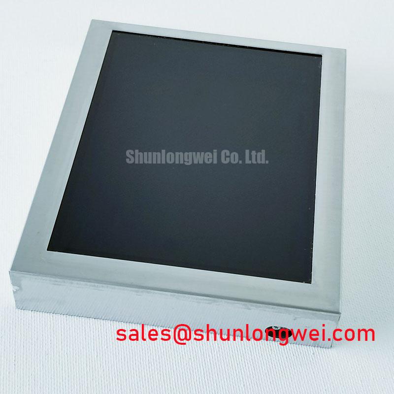
At the bench, display full-field light and dark test images if the installed application permits it. Look for persistent pixel defects, uneven illumination and colour shifts, then repeat the inspection after the assembly reaches a stable operating condition. Record the test pattern and viewing conditions so a later comparison is meaningful. The supplied specification does not establish a backlight technology, brightness rating or lifetime curve for this model, so a claimed backlight decay interval would not be a valid acceptance criterion.
A flicker or intermittent blank screen during nearby power switching may have more than one cause. As a Design Consideration, compare the panel supply waveform and communication activity with a known-good installation under the same operating condition; have the system engineer determine whether routing, grounding or filtering needs adjustment. The panel should not be described as independently meeting an equipment-level EMC requirement on that basis.
GP2500-SC41-24V Power and Protection Checks
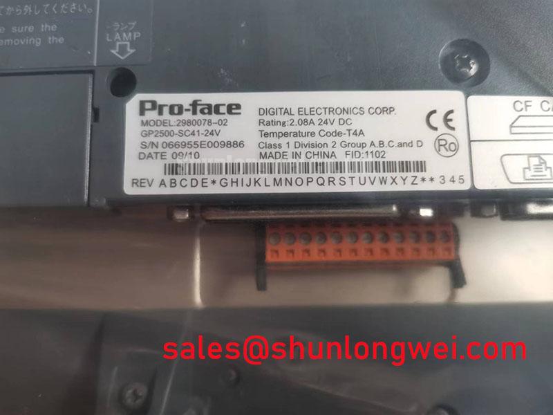
Measure the panel supply at its designated input during startup, steady operation and shutdown when a white screen or retained image is reported. Correlate the observed behaviour with the host equipment’s power sequence rather than assigning a cause from the image alone. The 24V text in GP2500-SC41-24V is part of the model designation; confirm the required supply, polarity and connector assignments from the original Pro-face and equipment documentation before making an electrical connection.
Fuse clearing energy and thyristor or diode withstand limits belong to the protected power circuit, not to this HMI assembly. No fuse characteristic or semiconductor surge limit is provided among the panel’s stated specifications, so those quantities cannot establish a protection setting or a damage guarantee for the GP2500-SC41-24V. A repair assessment should keep the panel’s input protection and the motor power-stage protection in their respective schematics.
For an intermittent display, examine the accessible harness and connector seating while the unit is unpowered. Check for skewed plugs, strained cable exits and contact movement caused by enclosure vibration. If a service drawing identifies an internal flexible connection as accessible to qualified personnel, follow that drawing’s handling procedure rather than assuming its pinout or bend tolerance. 💡 Bench Tip: Discharge the equipment and use ESD-safe handling before reseating a display cable, then align it squarely and secure its connector lock without pulling on the flex.
Signal-integrity checks should also follow the actual interface documentation. A differential-pair impedance or skew target taken from an unrelated display interface would be misleading here because the supplied facts do not identify a GP2500-SC41-24V signal pinout. Where a communication fault is suspected, probe the documented host interface and compare its waveforms with a working installation. A stable panel supply alongside missing or distorted traffic directs the next investigation toward the communication path without proving a single cause.
Assembly Integrity and Layout Considerations for GP2500-SC41-24V
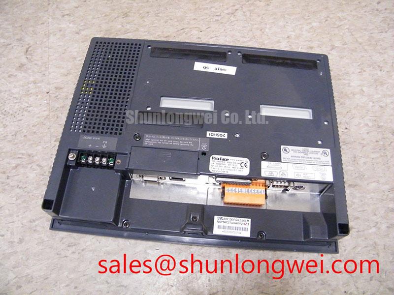
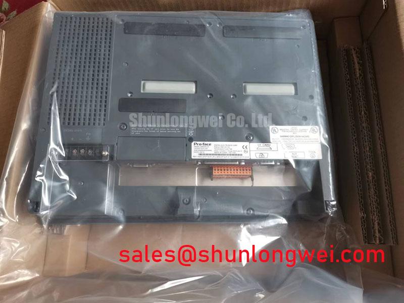
Inspect the GP2500-SC41-24V bezel-to-enclosure fit for uneven seating, loose restraints and cable pressure before investigating touch errors that appear after vibration or temperature changes. Confirm that the replacement opening, fastening arrangement and rear clearance match the original installation. Mechanical fit matters independently of whether the display powers up: a stressed assembly can alter touch operation or place avoidable load on its external connections.
A motor starter’s bypass contactor duty cycle and locked-rotor current limits must be established by its power-system designer. They are not panel parameters, and changing an HMI does not set the motor’s phase-angle control. In a soft-starter installation, evaluate this Pro-face assembly against the operator-panel requirements: physical dimensions, supply identification, communication interface, configured screens and touch functions. Do not infer compatibility from the model’s appearance or from a single successful power-up.
Run the available application through its normal screens and touch targets, noting any area that responds differently near the display edge. Repeat the check with the assembly mounted as it will be used; bench operation alone may not reveal a harness pulled tight by the enclosure. As a Design Consideration, route cables so enclosure movement does not repeatedly load a connector, and have the equipment engineer verify the permitted routing and strain relief against the service documentation.
Long-running static screens deserve an optical baseline. Photograph a uniform test image before and after the intended operating pattern, using comparable brightness and viewing conditions. If a faint residual image appears, check whether it changes after normal screen transitions rather than declaring permanent damage from one observation. The The Ultimate Guide to Industrial TFT LCD Technology provides background for interpreting display behaviour and test conditions; it does not supply an unverified lifetime rating for this specific assembly.
Field Diagnostics and Commissioning for GP2500-SC41-24V
Capture the GP2500-SC41-24V screen state, touch response and panel supply during the fault event, then compare them with the controller’s recorded status. A half-cycle surge-current rating and junction-temperature recovery test apply to power semiconductors in the host equipment, not to this HMI touch screen assembly. Those power-stage checks may be part of a soft-starter repair, but they cannot diagnose the panel without evidence linking the event to its supply or communication path.
For a panel that stays white after energisation, first distinguish absent screen content from absent backlighting by observing the display under the same conditions as a working unit. Check the documented input supply and host communication sequence, then repeat the startup while recording what appears and when. A white screen could accompany several faults; avoid replacing the assembly solely on that symptom. For a display that retains an image after shutdown, document the power-down sequence and whether the effect remains after the next normal startup.
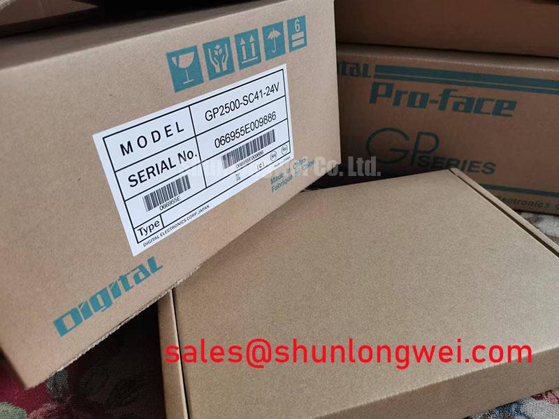
Commissioning should end with a reproducible record: model and nameplate photographs, connector positions, mounted condition, full-field optical images, touch-area results and the observed startup and shutdown behaviour. If the panel serves a motor soft-starter interface, confirm that displayed commands and alarms agree with the controller before returning the equipment to operation. Keep any power-stage surge or protection results in a separate test record so they are not mistaken for specifications of the GP2500-SC41-24V.