

Content last revised on October 14, 2026
Shielded FFC/FPC Flat Flexible Cable Grounding across 360-Degree Connector Shells
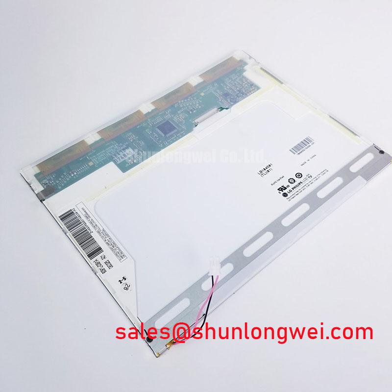
Pixel jitter close to a variable-frequency motor drive is commonly investigated at the cable shield path rather than at the glass itself. The FFC or FPC should maintain a short, continuous shield reference around the connector interface, while the cabinet bonding strategy should prevent high-frequency return current from sharing sensitive display signal conductors. A 360-degree shell termination is a system integration method, not a confirmed construction feature of the LB104S01-TL05.
During service evaluation, compare the display behavior with the drive disabled and enabled, then observe whether the noise changes when the cable is repositioned without applying mechanical stress to the connector. Common-mode ferrite components may be evaluated by the system designer where conducted or radiated interference is present, but their impedance profile and placement should be selected from measured noise behavior. The display signal reference, protective earth, chassis bond, and controller ground should be mapped separately before any bonding change is made.
For equipment such as a substation protection terminal or operator console, the cable route should remain separated from switching conductors and contactors where the enclosure allows. Differential-pair routing should preserve symmetry, and the receiving waveform should be checked at the panel end against a known-good signal path. A distorted eye opening, irregular clock transition, or noise correlated with drive switching may indicate a grounding or layout interaction rather than a failed display.
LED backlight ageing is best treated as a system maintenance subject. A 50,000-hour to 50 percent brightness curve is a Design Consideration sometimes used for constant-current backlight evaluation; it is not an official lifetime claim for this model based on the supplied product data. Record luminance, driver current, cabinet temperature, and operating duty together so that any decline can be separated from contamination, diffuser ageing, driver drift, or thermal accumulation. The principles of TFT construction and optical integration are also discussed in The Ultimate Guide to Industrial TFT-LCD Technology.
Mitigating Gray-to-Gray Response Time Escalation during Cold-Start Machine Power-Up
Cold-start evaluation should focus on the first several image transitions after the display controller enables video. Increased liquid-crystal viscosity can make gray-to-gray transitions appear slower at low temperature, while a controller that begins transmitting before the panel supply and backlight are stable can produce transient artifacts that resemble response-time failure.
The integrator should reproduce the actual power-up sequence used by the machine, including display enable timing, video clock startup, backlight activation, and any controller reset interval. Observe a moving grayscale pattern and static text separately. Smearing on moving transitions, incomplete frame content, and a temporary loss of synchronization point to different sections of the interface and should not be treated as one fault category.
For high-EMI installations, a differential-pair target such as 100 Ω ± 10% and a skew budget of 50 ps or less may be adopted as a Design Consideration when required by the selected LVDS interface and board stack-up. These values are not confirmed LB104S01-TL05 factory specifications. The system designer must align the actual transmitter format, receiver requirements, connector pinout, and impedance profile with the original panel documentation.
JEIDA and VESA data ordering should be checked at the controller and panel interface before changing firmware. A color-channel swap, bit-order mismatch, or incorrect clock polarity can create grayscale errors that remain visible after the unit reaches operating temperature. Use the original signal definition as the reference rather than assuming that a physically similar industrial LCD uses the same mapping.
💡 Pro Tip: Keep the positive and negative differential traces closely matched through the connector transition and validate clock-to-data timing at the receiving end under the actual enclosure noise conditions.
Evaluating Grayscale Inversion and Viewing Direction Alignment
Viewing-direction checks should be performed from the operator’s real seated and standing positions, not only from the center of the screen. TN-based displays can show grayscale inversion when viewed away from their preferred axis, while IPS and MVA products use different optical behavior; a replacement should therefore be assessed by actual image content, not by size or connector position alone.
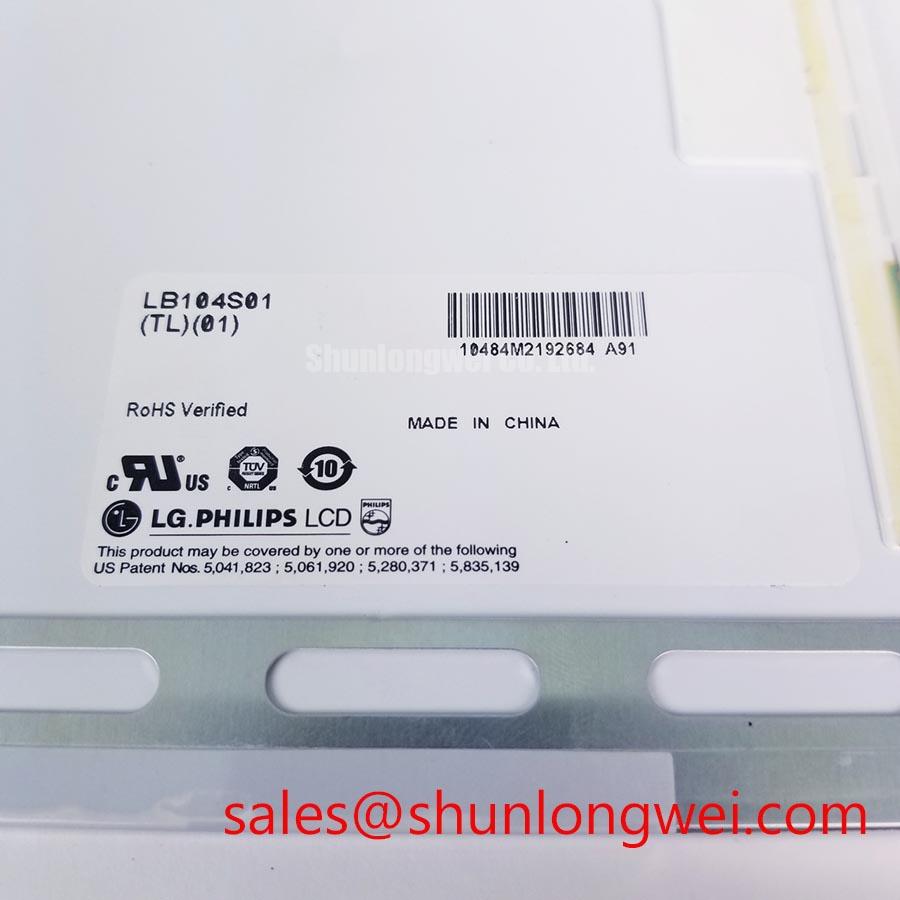
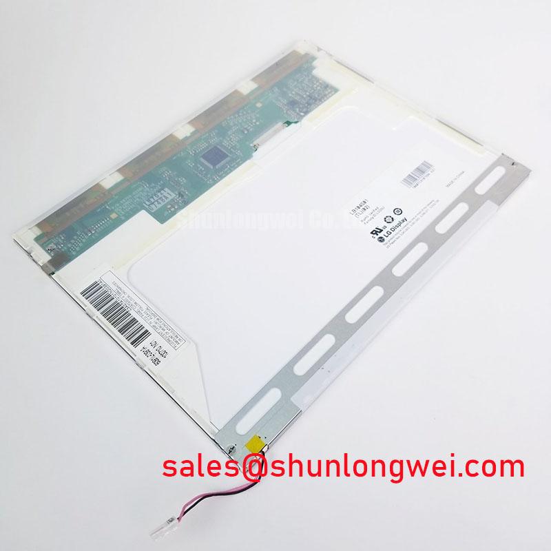
The LB104S01-TL05 product identity supplied here confirms an active-matrix TFT-LCD module, but it does not establish a TN, IPS, or MVA optical mode, nor does it confirm a symmetrical 85°/85°/85°/85° viewing cone. Those values must not be treated as specifications for this model. If a console places alarm text above or below the operator’s normal eye line, evaluate grayscale bars, red status indicators, and fine characters at the installed angle.
Surface treatment also affects field readability. Anti-glare etching can reduce reflected light in a bright control room, while excessive diffusion may soften small characters. The optical behavior of diffuser layers and brightness-enhancement elements is described in this reference on optical diffusers and brightness enhancement films. The external appearance of an installed panel should be compared under the actual cabinet lighting rather than under a bench lamp.
When a backlight controller supports PWM, a frequency range such as 200 Hz to 1 kHz may be considered during system tuning to reduce visible flicker or audible interaction with the driver. This is a Design Consideration for the control electronics, not an LB104S01-TL05 factory parameter. Verify duty-cycle behavior with a photodiode or suitable luminance instrument if alarm visibility depends on dimming linearity.
Suppressing Localized Thermal Gradients to Prevent Chronic Optical Yellowing
Thermal mapping around the narrow display edges should be completed before adding mechanical spreaders or changing backlight current. Local hot spots can create uneven luminance, color drift, adhesive stress, or accelerated ageing of optical elements, especially where the bezel restricts airflow and the backlight driver is mounted close to the panel.
An aluminum heat-spreader rail may be evaluated as a Design Consideration when temperature mapping shows a persistent edge gradient. Its contact pressure, electrical isolation, enclosure clearance, and effect on panel flatness require mechanical validation. The rail must not press on the active area or force the bezel out of alignment. A thermocouple map taken during cold start, steady operation, and repeated brightness changes is more useful than judging temperature by touch.
Terms such as L70 and B50 describe lifetime analysis methods, not confirmed performance ratings for this product. A constant-current driver evaluation can track luminance reduction, color coordinates, drive current, and local temperature over the intended duty cycle. Backlight open-circuit, short-circuit, and overvoltage responses should be checked at the driver output, because protection behavior belongs to the driver and system architecture unless explicitly stated in the panel documentation.
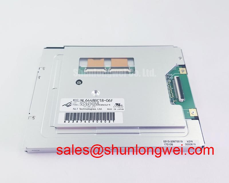
For sourcing comparisons, the NL6448BC33-50 may be reviewed as a separate same-class selection reference, but connector geometry, timing, optical mode, mounting dimensions, and backlight requirements must be compared individually before any substitution decision. The a-Si TFT technology reference provides useful background on active-matrix display behavior without establishing undocumented construction details for the LB104S01-TL05.
🔧 Bench Diagnostic: Disconnect display cables only with system power removed, then inspect the connector latch and shield termination before reconnecting the panel.