

Content last revised on September 10, 2026
Suppressing Localized Thermal Gradients to Prevent Chronic Optical Yellowing (Color Shift)
Localized heat near a narrow panel edge should be investigated as an enclosure-level condition rather than attributed to the AA104SG01 without measured evidence. A display can receive unequal heat from nearby power supplies, processors, backlight circuits, tightly fitted bezels, or restricted internal airflow. Over time, visible color variation or uneven brightness can be associated with several conditions, including light-source aging, optical stack changes, contamination, thermal stress, controller settings, or signal-path instability. Inspection should therefore begin with repeatable observations from a known display pattern instead of a single visual judgment.
Design Consideration: an aluminum support or heat-spreader rail can help distribute local enclosure heat when it is mechanically compatible with the panel frame and does not impose bending force on the TFT-LCD module. Its location, contact method, electrical isolation requirements, and thermal effectiveness must be determined by the equipment design. The panel documentation should also be checked before introducing conductive supports around connector areas or display edges.
When a display appears to shift color after warm-up, technicians should compare behavior at cold start and stabilized operating temperature, then inspect the controller board and backlight circuitry as separate possible contributors. A stable test image containing white, gray, red, green, and blue fields is useful for documenting whether the effect is uniform, edge-related, intermittent, or dependent on cable movement. This approach avoids assuming that a visible optical change has one fixed cause.
For digital video interfaces, transmitter clock quality and receiver timing margin are system conditions that can affect image stability. If the original host uses TTL or LVDS signaling, the system integrator should verify the required interface type, signal format, clock relationship, and data hold requirements from the original panel and controller documentation. JEIDA and VESA bit mapping must not be treated as interchangeable without confirmation, since incorrect mapping can produce abnormal colors, reversed grayscale behavior, or an apparently functional image with incorrect pixel data.
💡 Pro Tip: Route each differential pair as a controlled, closely coupled pair with matched path conditions, then verify the received waveform at the panel-side connector against the known-good signal path.
For equipment exposed to wide ambient changes, timing evaluation should include the expected operating temperature range of the finished assembly, not only a room-temperature bench test. A display module, cable harness, transmitter, and power supply may each respond differently to temperature. The practical objective is to preserve clean pixel-clock capture and stable data sampling while confirming that peak thermal conditions do not introduce enclosure distortion or localized loading on the module.
Optical Luminance Degradation Curve & CCFL-to-LED Modernization Retrofit Pathways
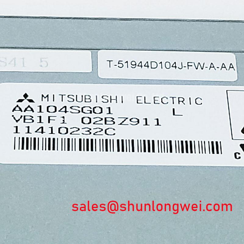
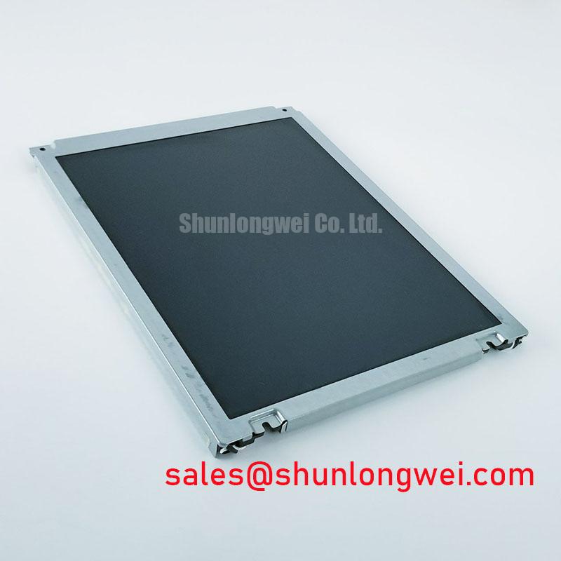
The supplied factory information identifies AA104SG01 as a TFT-LCD display module but does not confirm its backlight technology, backlight supply requirements, dimming method, luminance specification, or lifetime rating. Those values must be obtained from the original panel documentation and the installed equipment design before a backlight repair or modernization project is considered. It is not technically safe to assume that this specific model uses either CCFL or LED illumination.
When servicing a legacy display assembly, technicians can first establish whether the original backlight subsystem is operational by checking the original power architecture, control signals, cable routing, and image behavior under the manufacturer’s documented service procedure. A dark raster, unstable brightness, intermittent illumination, or noise from the display assembly can arise from different locations in the chain. Possible sources include the backlight driver, a cable connection, the host enable signal, an aged illumination assembly, or the main controller. Each should be isolated through measurement and comparison with documented conditions.
Design Consideration: CCFL and LED backlight systems use substantially different electrical architectures. A CCFL arrangement typically depends on a high-voltage inverter, while an LED arrangement generally requires current-regulated channels and compatible dimming control. Replacing one architecture with the other is a system redesign task, not a drop-in panel assumption. It requires confirmation of electrical isolation, thermal behavior, optical uniformity, mechanical clearance, dimming polarity, brightness control behavior, and the original display’s optical requirements.
PWM dimming is often evaluated in industrial display systems because duty-cycle control can influence perceived brightness. Audible behavior, visual flicker, camera artifacts, and low-brightness linearity depend on the complete driver, load, enclosure, and operating mode. Engineers should verify the actual dimming waveform and its interaction with the host control circuit rather than selecting a frequency from a generic rule. Natural text, fine graphical lines, and moving indicators are useful image patterns during this assessment because they can reveal flicker or luminance modulation that is less obvious on a static full-white screen.
Claims concerning L70, B50, MTBF, or a defined half-brightness operating duration require a traceable manufacturer specification or published reliability source for the exact illumination assembly. No field-life number should be assigned to AA104SG01 from panel category information alone. For equipment repair planning, the stronger method is to document present brightness, uniformity, dimming response, and thermal behavior, then compare those results against the original equipment acceptance criteria.
A retrofit review can also include nearby Mitsubishi Electric industrial panels where the equipment owner is evaluating a different mechanical or display architecture. The AA084VC01 can serve as a reference point for catalog comparison, but it must not be treated as a direct replacement without confirmation of physical dimensions, interface timing, power requirements, optical characteristics, and mounting compatibility.
Preventing Frame Lag & Image Smearing in Cryogenic Storage & Outdoor Industrial Facilities
Image smearing, slow menu redraw, or ghost-like transitions at low ambient temperature should be evaluated with the panel, host timing, power supply, and enclosure condition considered together. Liquid-crystal response can change as temperature falls, but an observed lag may also be influenced by display-controller configuration, frame update behavior, cable integrity, supply sequencing, or an application that is not refreshing the image as expected. The AA104SG01 factory information provided here does not state an operating-temperature range or response-time value, so suitability for cold storage or outdoor use must be confirmed from the original panel documentation.
When an industrial terminal is expected to remain installed in a cold environment, testing should reproduce the actual start-up sequence and normal image workload. A static boot logo is not enough to assess dynamic behavior. Alternating grayscale patterns, moving cursors, scrolling text, and changing alarm graphics can reveal whether the observed artifact follows temperature, cable movement, host load, or brightness setting. Recording the display behavior as the assembly approaches normal operating condition provides a more useful service record than assigning a single cause to each symptom.
Design Consideration: perimeter seals, display glass interfaces, mounting gaskets, and enclosure materials should be evaluated as a complete assembly when repeated thermal cycling is expected. Physical clamping pressure can change as materials expand or contract. The equipment designer should confirm that the mounting arrangement holds the module securely without concentrating force on the viewing area or connector region.
High-electromagnetic-interference locations require attention to the display signal route. Differential signaling is commonly used to improve noise rejection, but the resulting performance still depends on source termination, receiver requirements, cable construction, grounding strategy, connector quality, and uninterrupted return-path behavior. The required differential impedance and allowable pair skew must be taken from the interface requirements of the actual panel and controller. They are not established by the AA104SG01 product category alone.
Where a cable-related fault is suspected, inspect strain relief, connector retention, pin condition, shield termination, and routing near switching supplies or motors. An oscilloscope comparison at the transmitter and panel ends can help distinguish waveform degradation from controller-side image generation problems. If the equipment has a known-good parallel unit, a controlled cable and controller comparison is often more informative than replacing the LCD module first.
For wider environmental and enclosure evaluation practices, maintenance teams can consult Industrial Display & HMI Solutions as a practical reference for assessing display integration conditions. Any use in marine navigation consoles or other exposed industrial terminals remains subject to verified panel limits, enclosure sealing, power quality, and the host system’s environmental qualification requirements.
Surface Anti-Glare (AG) & Anti-Reflective (AR) Etched Coating for High Ambient Readability
Before specifying an anti-glare film, anti-reflective treatment, or replacement front cover, inspect the installed display under its real illumination geometry. Reflections may come from a protective window, scratched cover lens, angled bezel, wet surface, cabin lighting, sun exposure, or the display itself. The AA104SG01 official information supplied for this page does not confirm an anti-glare coating, anti-reflective coating, surface treatment, viewing-angle specification, contrast value, or brightness value. These features must therefore be verified from original Mitsubishi Electric documentation or the removed unit’s documented assembly records.
In applications such as a marine radar or navigation bridge console, high ambient light can make readability dependent on the complete optical stack rather than on panel brightness alone. A display behind an external window can suffer reflection losses even if the panel itself remains electrically functional. System integrators should assess the angle between the operator, window, panel surface, and dominant light source, then verify whether any proposed cover treatment changes color, haze, touch operation, sealing, or serviceability.
TN, IPS, and MVA are display technologies with different viewing characteristics, but no panel technology or viewing-cone specification should be attributed to AA104SG01 unless confirmed by the manufacturer’s documentation. Likewise, grayscale inversion, contrast variation, and off-axis color changes should be evaluated using controlled test images at the installed viewing position. This is particularly important for bridge-console layouts where operators may read displays from changing angles rather than from one fixed central position.
Surface modifications can create secondary integration issues. Added films or cover windows may affect heat retention, reflectance, adhesive aging, cleaning compatibility, and bezel fit. When evaluating an optical improvement, technicians should retain the original stack-up information and check that the modification does not interfere with frame grounding, drainage paths, gasket compression, or display removal procedures.
Backlight brightness decline should also be separated from front-surface reflection. A luminance measurement made through the installed cover can be useful for maintenance trending, provided that the same instrument position, screen pattern, ambient condition, and brightness setting are used for each comparison. Any claimed operating-life curve or brightness-retention percentage must be supported by the exact module or illumination-system specification; it cannot be inferred from the AA104SG01 model category.