Content last revised on October 1, 2026
High Voltage Striking Potential and Secondary Coil Insulation Testing
| Model | NL6448AC33-97D |
| Manufacturer | NEC |
| Product category | Industrial LCD display module |
| Display technology | TFT LCD active matrix color display module |
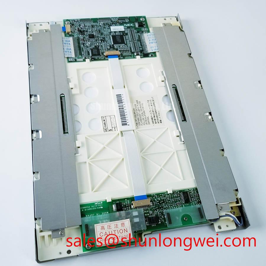
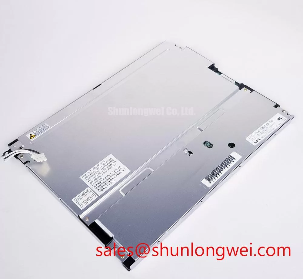
Measure the display assembly’s insulation behavior and backlight interface against the original equipment documentation before energizing any legacy high voltage circuit. The verified information for NEC NL6448AC33-97D identifies it as a TFT LCD active matrix color display module, but it does not establish a model specific high voltage ignition rating, CCFL transformer specification, insulation withstand value, or LED backlight drive requirement.
That distinction matters when a replacement panel is considered for a marine radar or navigation bridge console. A display using a cold cathode fluorescent lamp requires a dedicated inverter and secondary circuit assessment. The inverter output, transformer insulation, cable routing, connector spacing, and chassis bonding are system level properties. They should be compared with the original panel assembly rather than inferred from the display model number. Where an existing unit uses a constant current LED driver, the engineer should verify the required forward voltage range, current regulation method, enable logic, and dimming interface from the equipment service documentation.
Do not assign a 1500 to 1650 Vrms ignition value to this NEC module without a factory document that explicitly applies that value to the exact assembly. The same approach applies to a claimed 1000:1 PWM dimming ratio or a stated half life. These figures may belong to a driver, lamp, or different display family. They are not official specifications for this model unless the original technical documentation confirms them.
At the bench, inspect the backlight connector, transformer area, cable insulation, and chassis return for carbon tracking, salt contamination, discoloration, or mechanical damage. Use the equipment’s approved test method and isolation equipment. A failed ignition sequence may involve the inverter, lamp, connector, control signal, or power sequencing rather than the TFT cell itself. Record the enable state and brightness command while monitoring the known good unit, then compare the replacement assembly under the same conditions.
Timing compatibility also requires attention. Identify whether the host board transmits TTL or LVDS data, then confirm the connector pinout, pixel clock polarity, data mapping, and power sequencing from the original panel documentation. Do not substitute a JEIDA or VESA mapping by assumption. Clock jitter, setup time, and hold time must be evaluated across the actual industrial temperature range using the host transmitter and the replacement display together. The panel listing alone cannot establish the complete timing margin.
For related display sourcing, engineers can compare the same family context through NL6448AC33-17, while maintaining a separate electrical and mechanical compatibility review for every candidate. The NEC resource provides broader manufacturer information, but it should not be treated as a substitute for the exact panel documentation.
Single Vertical Hairline Defect and Column Driver Open Circuit Localization
Display a full white field, a full black field, and primary red, green, and blue fields while observing whether the vertical line remains fixed in the same screen position. This test-pattern bench check separates a persistent column related symptom from an intermittent image, backlight, or signal path problem without assigning a single cause prematurely.
A line that remains visible across all test colors deserves inspection at the panel edge, flex connection, and host interface. A dark line that changes with image content can involve data mapping, timing, connector contact, or the source board. A bright line visible only under certain illumination conditions may require a separate optical inspection. Record the defect location in relation to the active image area and compare it with the known good display using identical graphics and timing.
A 45 degree flashlight inspection can help distinguish a light emission problem from an image formation problem. With the display unpowered, examine the surface and edge area using oblique light for scratches, pressure marks, contamination, or damage around the bonded driver region. With the system operating, use controlled ambient illumination to determine whether the line is visible because the backlight is uneven or because the liquid crystal cell is receiving an abnormal column signal. This technique is a localization aid, not proof of a particular internal failure mechanism.
Do not describe a visible line as a COG micro fracture solely from appearance. The panel’s internal bonding construction and repairability are not established by the supplied factory parameter set. A controlled comparison of source data, panel power, timing, and physical flex response is more useful. If gently securing the cable changes the symptom, stop mechanical manipulation and inspect the connector and mounting pressure, because additional flexing can create a new fault.
Use the host board’s test pattern or an external pattern generator only when its signal format is known to match the display. Verify the active resolution, refresh behavior, color depth, and data ordering. If the pattern is not correctly aligned with the panel interface, a false line, missing color, or unstable image can be mistaken for a column driver defect. The system integrator should verify all electrical and timing requirements from the original NEC panel documentation.
Replacement evaluation should include the mounting frame, viewing window, connector orientation, cable bend path, and pressure points around the glass. A panel can be electrically responsive while remaining mechanically unsuitable for the enclosure. For broader installation guidance covering industrial display and HMI integration, see Industrial Display & HMI Solutions.
Surface Anti Glare and Anti Reflective Treatment for High Ambient Readability
Inspect the panel through the actual enclosure window under the intended lighting direction, then compare black level, white field uniformity, reflected highlights, and viewing angle from the operator position. The supplied verified data identifies an active matrix TFT color module, but it does not confirm an anti glare coating, anti reflective treatment, contrast ratio, optical luminance, viewing cone, or sunlight readability value for this exact model.
This prevents an unsuitable optical assumption during marine console replacement. A surface finish may reduce reflected detail while also changing apparent sharpness, haze, or touch surface behavior. A protective window, gasket, polarizer condition, and enclosure angle can dominate the result. Assess the complete stack as installed rather than judging the bare panel under laboratory lighting.
TN, IPS, and MVA are not interchangeable descriptions. The correct panel construction and optical mode must be established from the original documentation. Do not assign a symmetric 85 degree viewing specification or claim a particular grayscale inversion behavior unless the factory data for NL6448AC33-97D states it. The same caution applies to a contrast ratio greater than 500:1 at 50000 lux. Ambient illumination, measurement geometry, surface reflection, and the host optical window all influence the observed value.
For a practical readability check, display neutral gray ramps, small text, navigation symbols, and high contrast alarm graphics. View them from the normal operator position and from the angles used during service access. Inspect for grayscale inversion, color shift, loss of shadow detail, and reflected sky or deck lighting. Repeat the check with the enclosure window, seal, and mounting bezel installed. If the display is being evaluated for a harsh marine radar or navigation bridge console, salt residue and cleaning methods should also be considered because surface contamination can increase glare and reduce apparent contrast.
Use a calibrated optical measurement method when a contract or equipment specification requires a numeric brightness or contrast result. A visual pass at the bench cannot establish compliance with a system requirement. Information from Tianma Industrial TFT Display Solutions can provide general industrial display context, but it does not replace the exact specification for this NEC model.
Field Alert: Disconnect power before removing or inserting the display cable, because contact movement during live insertion can damage the panel interface or host electronics.
Eye Diagram Voltage Margin and Differential Noise Verification in High Vibration Bays
Capture the panel data waveform at the display connector while the host system runs its actual graphics pattern, then compare signal integrity and timing stability with the known good assembly. Where a differential interface is confirmed, compare its eye opening and common mode behavior as well. This helps separate a display panel problem from cable routing, connector contact, grounding, or host transmitter behavior.
The NL6448AC33-97D listing does not provide a confirmed LVDS or TTL interface definition, cable length, connector pin assignment, differential impedance, common mode range, or receiver timing limit. These values must be taken from the original panel documentation and host board design. Do not infer the interface from the physical connector alone. Different display families can use similar connectors with different power, clock, data order, and control assignments.
For a differential interface, preserve pair relationships through the complete cable route, avoid unnecessary stubs, and maintain a controlled return path. The target impedance and allowable skew are system design parameters that should be confirmed against the transmitter, cable, connector, and receiver data. During testing, compare the clock and data eye at the panel end rather than relying only on a waveform measured at the host board.
Variable frequency motor drives and servo equipment can introduce conducted and radiated energy into long display cables. Review shield termination, chassis bonding, connector backshell contact, and cable separation from switching power and motor conductors. A ferrite component may be useful when selected from measured common mode behavior, but it should not be added as an automatic remedy because it can also affect signal integrity and edge behavior.
Horizontal noise bands, intermittent color blocks, or image instability may be related to supply ripple, reference movement, cable coupling, clock margin, or incorrect data mapping. Check the panel supply at the connector during brightness changes and host load transitions, then correlate the display symptom with the measured waveform. A stable image with a substitute cable does not by itself prove the original cable is defective; repeat the test with controlled routing and the same mechanical vibration conditions.
Mechanical integration is part of signal integrity. Confirm that the frame does not press on the glass, that the cable is not sharply folded at the connector, and that vibration does not pull the panel cable against the enclosure. The final acceptance test should combine image patterns, temperature exposure, enclosure installation, and representative electrical noise. Engineers evaluating a compatible display option may review NL8060BC31-41 as a separate display solution, but its electrical interface and backlight requirements must be assessed independently.
Source the NEC NL6448AC33-97D by matching the verified manufacturer, product category, TFT active matrix construction, enclosure geometry, interface documentation, and host system timing. The final installation decision remains dependent on the original equipment drawings and measured compatibility at the panel connector.