

Content last revised on September 13, 2026
G121SN01 V402 AUO TFT-LCD Industrial Display Panel
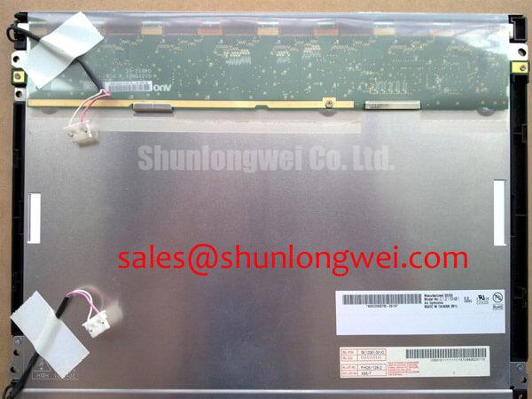
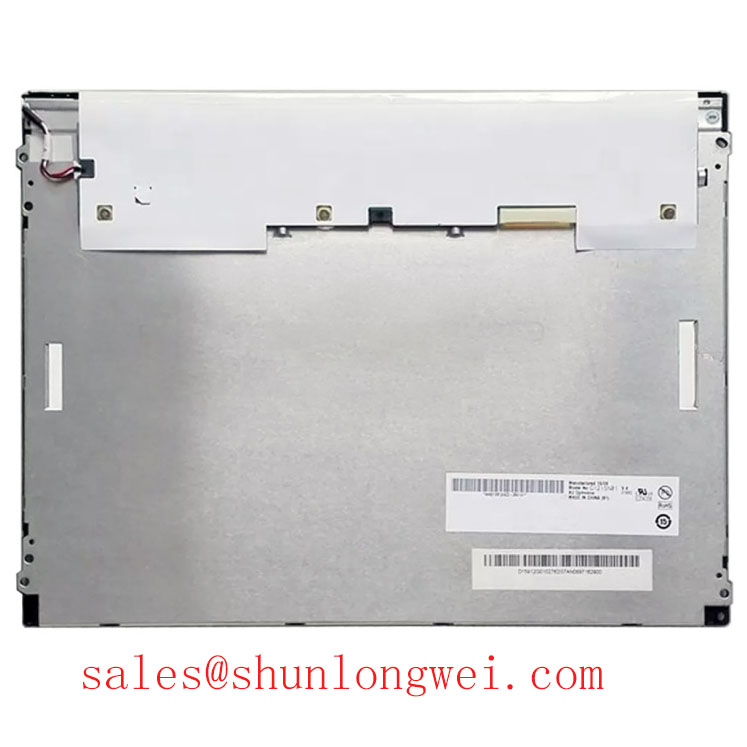
Use an ESD-safe bench, inspect the glass edges and connector area, then compare the identification label with the service record before applying power to the G121SN01 V402. The unit is identified as an AUO TFT-LCD Display Module for industrial display integration. The supplied factory context classifies it as an Industrial Grade LCD/HMI Panel. Full panel specifications should be confirmed against the original documentation before integration.
For an incoming inspection technician, the first objective is not to assume compatibility from the model number alone. Confirm the mechanical opening, mounting points, connector position, display orientation, host controller interface, backlight arrangement, and power requirements against the original panel documentation. The available product information does not confirm a complete electrical pinout, native resolution, active-area dimensions, luminance value, viewing-angle technology, operating-temperature rating, or backlight drive specification. Those values should be obtained from the original panel documentation or the equipment manufacturer before integration.
| Manufacturer | AUO |
| Model | G121SN01 V402 |
| Product category | Industrial Grade LCD/HMI Panel |
| Construction classification | TFT-LCD Display Module |
| Specification status | Full specifications require confirmation from the original panel documentation |
Mechanical Stress and Glass Substrate Fracture Prevention
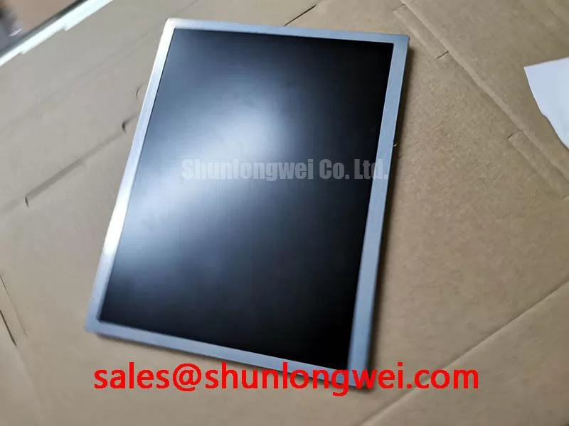
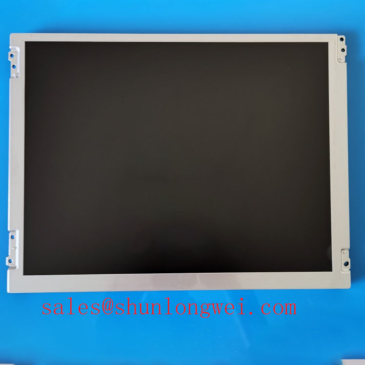
Place the panel on a clean, level, electrically insulated surface and begin with an unpowered visual inspection. Look across the active area under diffuse illumination, checking for edge chips, pressure marks, glass cracks, uneven frame loading, connector damage, and signs that the flexible cable has been bent sharply near its bonded region. A display that is visually intact can still require signal-path verification, so the inspection should be followed by a controlled image test using the intended controller.
A practical three-stage primary-colour test uses full-screen red, green, and blue images, provided by the known-good host system. Each colour should be observed across the complete active area rather than judged from a small window. Record fixed dark points, bright points, vertical lines, horizontal lines, intermittent columns, and areas that change when the cable or frame is gently observed during operation. Mechanical pressure should not be applied to the glass or bonded cable. The purpose is to document repeatable behaviour, not to force a temporary contact.
A flashlight held at approximately forty-five degrees can help separate an illumination problem from a line defect. With the display showing a uniform colour, inspect the panel from an oblique angle and look for a dark shadow that follows the shape of a local backlight or optical non-uniformity. A line that remains sharply aligned with the pixel matrix is more relevant to the signal or bonded-driver path. This method is a screening aid rather than proof of a particular internal failure mode; confirmation should come from comparison with a known-good signal path and the panel’s approved controller.
Mechanical stress risk is mainly an integration concern. Uneven bezel pressure, a connector mounted out of plane, cable strain, or a chassis that flexes during screw tightening can transfer load into the glass assembly. When installing the AUO module, designers should support the panel through its intended mounting features, leave the cable with a natural service loop, and verify that the enclosure does not press against the active area. The correct mounting hardware and tightening method remain system-defined unless specified in the original mechanical drawing.
Low-temperature testing needs a controlled ramp rather than an immediate transfer from room temperature to a cold chamber. Liquid-crystal response can become slower as temperature falls, and the resulting grey-transition delay may be mistaken for a timing fault. If the target equipment includes a CNC operator panel or robot teach pendant used in a cold environment, test the complete display, controller, cable assembly, and heater control as one system. The available factory information for this product does not confirm a −20°C or −30°C operating rating, so those conditions must not be treated as an official limit for this model.
💡 Bench Tip: Keep the operator grounded through ESD control and lock the display cable evenly and squarely; never insert or remove the cable while the system is powered.
Optical Luminance Degradation and Backlight Retrofit Evaluation
Record optical performance with the same test image, measurement position, display warm-up condition, and controller settings each time. A visual comparison can identify gross luminance variation, colour imbalance, corner shading, or a bright region near the edge, but it does not establish a luminance specification. The supplied factory parameters identify the product as a TFT-LCD display module but do not provide a confirmed luminance value, backlight lifetime, colour-temperature tolerance, or half-life rating.
Before evaluating a retrofit, identify the original backlight architecture from the equipment documentation and wiring. Do not assume that a replacement panel uses the same lamp, LED arrangement, connector, driver, dimming method, or enable sequence. A CCFL inverter and a constant-current LED driver are different electrical subsystems. The system integrator should verify the required supply voltage, current, connector pinout, enable signal, dimming method, and protection behaviour from the original panel documentation.
For a CCFL-based system, cold ignition behaviour should be assessed at the inverter and lamp assembly under controlled conditions. Audible noise, delayed start, intermittent illumination, or a momentary flash can involve the lamp, inverter, wiring, grounding, or enclosure resonance. The available information does not confirm a specific high-voltage ignition requirement for G121SN01 V402, so values such as lamp ignition voltage must not be assigned to this model without a supporting specification.
For an LED modernization path, the replacement driver should be evaluated for constant-current regulation, dimming compatibility, thermal behaviour, conducted noise, and startup sequencing. A PWM dimming ratio or frequency should be selected by the system engineer after checking the driver data sheet, camera sensitivity, human visual requirements, and controller timing. Claims regarding a 1,000:1 dimming ratio or more than 50,000 hours of service life are not official specifications supplied for this product and should not be used as acceptance criteria without documented evidence.
Optical measurements should include a centre reference and multiple edge locations so that local heating or enclosure shadowing is not confused with panel ageing. If an LED retrofit changes the heat distribution behind the display, inspect the rear surface and surrounding electronics during thermal testing. Avoid adding pressure, adhesive, or unverified optical layers to the TFT-LCD module. For repair planning, engineers can review the neutral technical reference on industrial TFT-LCD technology before approving a backlight or controller change.
EMC Assessment Through Backplate Bonding and Grounding
When a panel is installed near a variable-frequency motor drive, servo amplifier, or switching power supply, begin the EMC assessment with cable routing and bonding. Keep display signal wiring separated from high-current switching conductors where the enclosure permits, avoid unnecessary cable loops, and make the shield termination strategy consistent at the equipment level. The G121SN01 V402 product information does not certify the finished machine to CISPR Class A or Class B; EMC compliance belongs to the complete assembled system.
Inspect the FFC or LVDS path for incomplete insertion, skewed locking, damaged contacts, and mechanical movement at the connector. Pixel jitter, intermittent lines, or horizontal noise bands can have several possible sources, including signal integrity, controller timing, grounding, power ripple, cable damage, or interference from nearby switching hardware. Compare the display clock and data behaviour with a known-good cable and controller, then use an oscilloscope only with suitable probing practice so the measurement setup does not add excessive capacitance or create a new ground path.
Where the controller documentation specifies differential signalling, maintain the intended pair geometry through the cable and connector transition. A commonly used differential interconnect target is 100 ohms, but that value must be confirmed for the actual interface and cable assembly rather than assumed from the panel model. The transmitter clock relationship, data hold time, receiver setup margin, and allowable skew should be checked against the controller and timing documentation across the intended temperature range.
Backplate bonding can reduce unpredictable reference movement when it is designed as part of the enclosure grounding scheme. A multi-point or star-ground arrangement may be considered where it provides a low-impedance return for unwanted high-frequency currents, but the final arrangement depends on chassis construction, isolation requirements, cable shields, and safety architecture. Ferrite components can also be evaluated for common-mode suppression, provided their impedance characteristics match the interference spectrum and do not disturb the display signal.
For a CNC operator panel or robot teach pendant, the repair team should test the display with the actual controller, cable length, enclosure, motor-drive state, and backlight operating condition. A quiet bench result does not establish compliance in the completed machine. Document the image pattern, drive operating state, cable routing, grounding configuration, and observed noise so that later changes can be compared without relying on memory.
Temperature Qualification and Sub-Zero Liquid-Crystal Response
Temperature qualification should start by confirming which limits belong to the panel and which belong to the controller, backlight, cable, adhesive, and enclosure. The supplied product context does not publish a confirmed operating range of −30°C to +85°C for G121SN01 V402. Those temperatures may be used as design evaluation points only when the original documentation and the complete equipment specification support them.
During a cold test, monitor image uniformity, colour transition behaviour, startup time, flicker, line stability, and recovery during the temperature ramp. Increased liquid-crystal viscosity at low temperature can extend grey-to-grey transitions, while controller timing or backlight startup can create separate symptoms. A slow transition alone should not be assigned to one cause. Compare several grey levels, primary colours, and moving test patterns, and allow the panel to stabilize before recording observations.
Heater strips or enclosure warming systems require system-level control. Their location, thermal gradient, control sensor, and safety limit should be evaluated so that the panel warms evenly without creating local optical non-uniformity. The display should be tested through repeated temperature changes with the cable and mounting hardware installed, because mechanical expansion can alter connector seating and frame stress. Perimeter sealing materials and enclosure gaskets also require confirmation from their own suppliers; their behaviour must not be inferred from the AUO model number.
At elevated temperature, inspect the backlight region, connector area, and controller board for heat concentration. Any airflow path, thermal pad, bracket, or shield added during installation should be checked for mechanical pressure and unintended optical shadowing. If brightness control uses PWM, verify the actual controller and driver requirements before selecting a frequency or duty-cycle range. The product information provided here does not confirm a specific PWM frequency, duty-cycle linearity, or dimming performance for this display module.
For replacement planning, compare the original mechanical drawing and electrical documentation with the proposed unit before purchase approval. The G104VN01 V1 may be reviewed as a separate comparison reference, but substitution remains dependent on dimensions, interface, timing, mounting, optical requirements, and the host equipment’s acceptance test. The product page for G121SN01 V402 should be used alongside the original equipment documentation when preparing a repair or integration checklist.