Content last revised on October 8, 2026
AUO G121STN02-1 Identification and Maintenance Preparation
Before disconnecting an operator-station display, isolate the equipment under the site’s approved maintenance procedure and confirm that the installed panel label reads G121STN02-1. Record the connector orientation, cable routing, mounting arrangement and any separate touch-controller connections before disturbing the assembly. For a petrochemical Zone 2 operator station, opening the enclosure also requires the applicable hazardous-area work controls; a display replacement must not compromise the complete station’s protection measures.
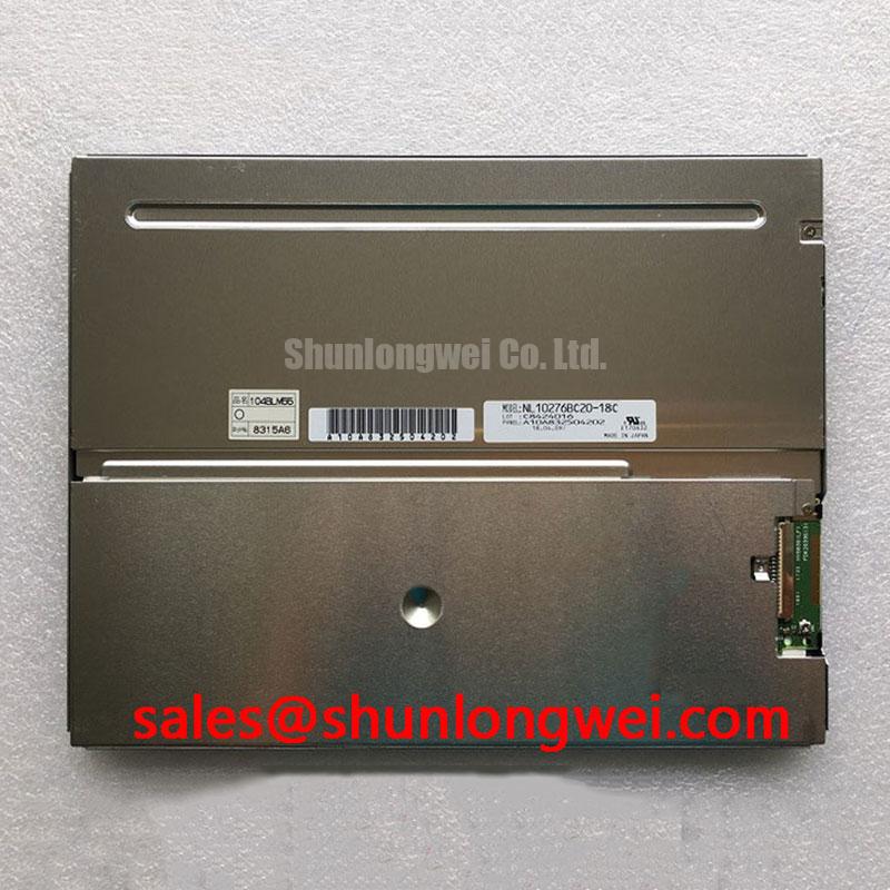
The AUO G121STN02-1 is identified as an industrial LCD/HMI panel in a TFT-LCD display module format. These product identifiers establish the component being assessed, but they do not establish its electrical interface, temperature limits, optical performance or suitability for a particular hazardous-area enclosure. Maintenance and purchasing decisions should therefore distinguish the panel itself from the controller, backlight supply, touch overlay and protective housing surrounding it.
| Product identification | Specification | Engineering relevance |
|---|---|---|
| Model | G121STN02-1 | Match the complete designation when assessing an installed module. |
| Manufacturer | AUO | Use the corresponding manufacturer documentation for integration limits. |
| Product category | Industrial LCD/HMI panel | Assess compatibility with the existing operator-station display assembly. |
| Module format | TFT-LCD display module | Treat the display, touch system and enclosure as separate integration items. |
Temperature Operating Margin and Sub-Zero Display Response
Start the temperature assessment at the installed assembly, not at the outdoor weather reading. An operator station can experience heat from its controller, power conversion circuitry and enclosed backlight system while its front window remains exposed to a cooler environment. As a Design Consideration, assess panel-area temperature during representative operation and compare it with the module’s documented operating limits. Do not adopt a temperature range from another industrial display as the G121STN02-1 rating.
Cold liquid-crystal response can produce visible trailing or slower transitions without necessarily indicating a failed panel. Evaluate the display with the same moving graphics, alarm transitions and text changes used by the actual HMI. Compare the behavior after thermal stabilization with its behavior during startup. This separates temperature-dependent response from persistent faults more effectively than judging a single static image. A numerical gray-to-gray response claim requires the manufacturer’s test conditions and specification.
Thermal cycling also affects the surrounding assembly. Inspect enclosure gaskets for hardening, displacement and loss of contact, especially where cables enter the housing. Oil residue and dust around a seal can conceal deterioration rather than demonstrate effective sealing. As a Design Consideration, investigate condensation risk when a cold station is brought into a warmer, humid environment. Any heater, ventilation arrangement or humidity-control measure should remain consistent with the complete station’s approved construction.
Temperature-related image interruption should also prompt inspection of the signal path. Confirm the actual interface and connector assignment before evaluating cable continuity or signal quality. Where the documented interface uses differential signaling, preserve the specified pair routing and termination, and assess waveform quality against the receiver requirements. Neither a numerical impedance target nor a timing-skew allowance should be assigned to this module without its interface specification.
For a Zone 2 installation, the LCD module’s industrial classification is not evidence of explosion-protection approval. The integrator should verify the complete operator station’s applicable certification, permitted component changes and temperature conditions. The distributor’s Industrial Display & HMI Solutions guide provides broader integration context, while the equipment documentation remains the reference for the particular installation.
Viewing-Angle and Surface-Reflection Checks for Multi-Angle Consoles
Assess readability from the positions operators actually occupy: directly in front of the station, beside a valve-control area and at the normal standing height. Use alarm colors, shaded process graphics and small text rather than a full-white screen alone. The G121STN02-1 identification does not establish an IPS or MVA architecture, a symmetric viewing-angle specification or a particular surface treatment; those characteristics should be confirmed before they become purchasing criteria.
As a Design Consideration, off-axis contrast and grayscale changes should be checked separately from reflections. A display can retain readable contrast at an angle yet become difficult to use because a protective window reflects overhead lighting. Conversely, a low-reflection front surface cannot correct an unfavorable viewing direction. Evaluate the assembled station with its actual window and touch overlay installed, since these additional layers affect the result seen by the operator.
Anti-glare and anti-reflection treatments address different optical effects. A scattering surface can soften reflected images, while an anti-reflection treatment can reduce reflected light at treated interfaces. Neither feature should be attributed to this AUO module without supporting documentation. If the station already has an optical treatment, follow its cleaning instructions: abrasive cleaning or incompatible solvents can damage the front assembly and make a serviceable display appear hazy.
Backlight brightness should be assessed alongside the existing driver and its control signals. Establish whether dimming responds normally, whether the supply remains stable and whether brightness varies with equipment operating conditions. A dim image does not independently identify a worn backlight. Driver behavior, the optical stack, controller settings and the front window can all affect perceived brightness. No numerical backlight lifetime or brightness-maintenance interval is established by the supplied product identification.
When comparing display assemblies, the TX20D200VM2BVA represents a separate display option whose own power, interface and backlight requirements must be evaluated independently. It should not be treated as a G121STN02-1 backlight driver or a drop-in companion. For either assembly, protection functions such as open-load detection, short-circuit handling and overvoltage shutdown belong to the documented driver implementation, not to an assumed feature set.
Full-Screen Color Screening and Background Uniformity Diagnosis
Use a controlled bench image sequence before reinstalling the G121STN02-1. First, display solid red, green and blue fields to inspect individual color-channel behavior. Next, inspect white and intermediate gray backgrounds for shading and localized nonuniformity. Finally, examine a dark background and a text or grid pattern for bright points, line defects and image instability. Keep controller settings, viewing position and ambient lighting consistent so that changes remain comparable.
This is an Engineering Recommendation for functional screening, not a manufacturer-defined acceptance standard. Record the location and persistence of visible defects, and apply the relevant panel acceptance criteria or equipment service requirements. A single bright or dark point should not be assigned a failure mechanism merely from its appearance. Similarly, an intermittent line warrants investigation of the controller, cable and panel connection before attributing it to an internal module defect.
If the screen appears dark, determine whether an image is still present before replacing the panel. Under suitable bench conditions, oblique illumination can help reveal faint graphics when backlight illumination is absent. This observation supports separating image generation from illumination, but it does not identify a specific failed component. Check the documented backlight enable, dimming command and supply path, then examine available driver fault indications against the driver’s own documentation.
Open-circuit, short-circuit and overvoltage indications require particular care. Where the installed driver provides these signals, record their state and operating conditions rather than repeatedly cycling power to clear them. As a Design Consideration, verify that protection behavior is compatible with the actual backlight load and wiring. Do not bypass a protection function to force illumination, and do not infer a normal voltage or current from another panel’s service data.
Touch performance should be tested independently of LCD image quality. Establish the installed touch technology and controller configuration before evaluating operation with gloves or surface moisture. Check representative control targets, edge areas and unintended activation under the equipment’s permitted conditions. Water tolerance and glove sensitivity are properties of the complete touch implementation; they are not established by the G121STN02-1 model designation. Keep these observations separate in the service record so a touch problem does not become an unsupported LCD replacement decision.
Chassis Fastening, Optical Mura and Enclosure Fit
Before tightening the display assembly, compare its mounting points, connector clearance and bezel opening with the equipment drawing. The front frame should support the intended mounting features without pressing against the active display area or forcing the module into a distorted position. Inspect the bracket and seating surfaces for debris, bent edges and uneven contact. These mechanical checks are especially important where vibration has loosened surrounding hardware or shifted cushioning material.
No mounting screw size, fastening torque or outer-envelope tolerance is established by the supplied G121STN02-1 identification. As a Design Consideration, use the limits specified for the module, bracket and fastener arrangement rather than applying a generic torque value. Where the equipment instructions specify an alternating tightening sequence, follow it while checking that the assembly remains seated without visible distortion.
Pressure-related optical nonuniformity, often described as mura, should be evaluated with repeatable gray and dark backgrounds. Compare the image before mounting and after the assembly is secured. A change associated with fastening can justify examining mechanical loading, but it does not prove damage to a particular internal layer. Inspect bezel contact, cable tension and bracket alignment before deciding whether the module itself requires replacement.
⚠️ Maintenance Note: Inspect vibration pads and enclosure gaskets during scheduled service, and replace deteriorated parts according to the equipment manufacturer’s instructions rather than compensating with additional screw tightening.
For replacement assessment, the G104VN01 V1 can be included as a separate candidate in a documented comparison, not assumed to be interchangeable. Compare verified active area, outline dimensions, resolution, interface, connector assignment, mounting features and backlight requirements. Retain the installed configuration until those checks are complete, then repeat image, touch and enclosure inspections after assembly so that fit and function are assessed together.