Content last revised on September 12, 2026
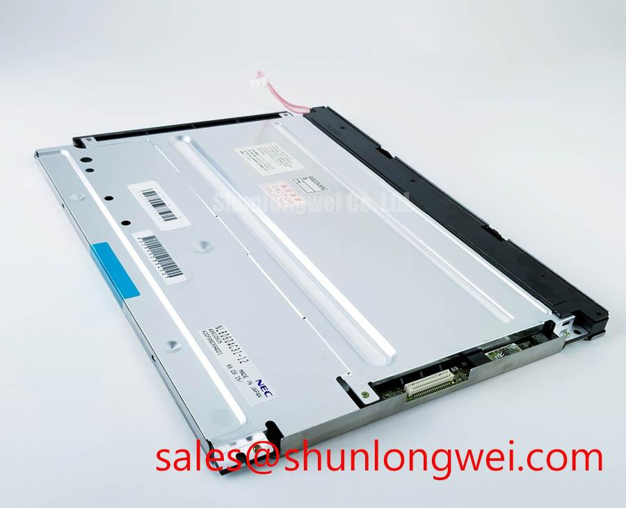
AA104XD12 Mitsubishi Electric Industrial TFT LCD Display Module
Begin the bench check by inspecting the AA104XD12 housing, connector area, and visible panel surface for impact marks, contamination, or mechanical distortion before applying power. Confirm the replacement identity against the original equipment documentation, then verify the display interface, supply requirements, backlight arrangement, and mounting envelope before connecting it to a host controller.
The AA104XD12 is a Mitsubishi Electric TFT LCD Display Module classified for industrial LCD and HMI panel applications. The available factory information identifies the product category, manufacturer, and display module construction, while the detailed electrical interface and dimensional values must be confirmed from the original panel documentation and equipment service records. This distinction matters when a display is being evaluated for a repair rather than selected for a new design.
| Parameter | Available specification status |
|---|---|
| Model | AA104XD12 |
| Manufacturer | Mitsubishi Electric |
| Product category | Industrial LCD display module |
| Construction | TFT LCD Display Module |
| Specification status | Product identity and category identified; detailed specifications require verification |
| Interface, supply, optical, and mechanical values | Verify from the original panel documentation before integration |
Because the confirmed product data does not state a universal input voltage, LVDS or TTL assignment, backlight current, resolution, viewing direction, or external dimensions, those values should not be inferred from the model number. The system integrator should verify the required supply voltage from the original panel documentation. The same verification applies to connector keying, cable orientation, timing configuration, and any touch or control electronics fitted around the display.
Eye Diagram Voltage Margin and Differential Noise Floor Verification in High Vibration Bays
When the AA104XD12 is installed near variable frequency drives, servo amplifiers, switching power supplies, or long motor cables, begin signal verification at the display connector and work backward toward the host controller. Record the cable construction, shield termination, connector orientation, and chassis bonding arrangement before changing the wiring. A display fault that appears as pixel jitter, intermittent horizontal noise, or unstable image locking can involve the signal path, grounding arrangement, power rail disturbance, or timing configuration, so a controlled comparison with a known good unit is more useful than assigning a single cause.
For an LVDS implementation, inspect the differential pairs as a complete transmission path. Pair polarity, lane order, clock assignment, data format, and connector pin numbering must match the panel documentation. The use of JEIDA or VESA data mapping is system dependent; selecting the wrong mapping can produce incorrect grayscale, abnormal colors, or an image that appears stable but is electrically misinterpreted. If the source uses TTL rather than LVDS, the voltage levels, return paths, edge rates, and cable arrangement require a separate compatibility check. Do not assume that a cable suitable for one signaling method can be transferred to the other.
A differential probe and oscilloscope can be used to compare the clock and data eye openings at the host output and at the display input. Check whether common mode movement, ringing, or edge displacement changes when the nearby drive enters a switching state. The transmitter clock jitter margin and data hold relationship should be reviewed across the specified operating temperature window of the original assembly. If the panel documentation does not provide those limits, use the host controller specification and a verified reference panel as the measurement baseline rather than creating a replacement limit.
A 360 degree shielded FFC or LVDS cable arrangement may be considered where the mechanical design supports continuous shielding and reliable chassis bonding. The final grounding method remains dependent on the enclosure, protective earth strategy, and location of high energy switching conductors. Common mode ferrite suppression can also be evaluated as a Design Consideration when conducted or radiated interference is observed, but its impedance behavior must be checked against the signal bandwidth and power return path. Filtering that improves noise at one operating point can affect edge quality or startup behavior at another.
Route the display cable away from motor conductors and high di/dt switching loops wherever the enclosure permits. Keep the differential pair geometry consistent through connectors and board transitions, and minimize unnecessary stubs. The commonly used differential target of 100 ohms is a board and interconnect Design Consideration, not a confirmed factory specification for this display module. The PCB designer should validate impedance, skew, and eye opening with the actual controller, cable, connector, and enclosure combination.
For a replacement assessment, compare the AA104XD12 with the same equipment’s original timing waveform, screen initialization sequence, and image content. The Mitsubishi Electric AA084VC01 may be reviewed as a separate display option when the application requires a different size or interface evaluation, but physical and electrical interchangeability must be established from documentation rather than assumed from the product family.
Single Vertical Hairline Defect and Sub Pixel Column Driver Open Circuit Localization
A single vertical line should first be documented with a uniform white field, black field, and primary color screens. Use the same source timing and image generator for each test so that a graphics pipeline problem is not confused with a panel defect. A line that remains fixed while the displayed content changes deserves closer inspection around the panel connector, flexible interconnect, and column drive area, but the observation alone does not establish a specific internal failure mechanism.
The practical bench sequence is to confirm the host image output, reseat the display cable only with power removed, and compare the suspected panel with a known good signal path. Then perform the three color checks using red, green, and blue fields, followed by dark and bright patterns. Note whether the line changes in brightness, color, width, or visibility. These observations help separate an input data issue from a localized pixel or column response problem without relying on unsupported resistance thresholds.
An angled flashlight inspection in a controlled ambient light condition can help determine whether a dark feature is associated with the emitted display image or with a surface, diffuser, or illumination irregularity. This is a visual localization method, not proof of a particular internal construction. Avoid pressing the active area or flex regions during this check, since mechanical force can change the symptom and complicate the diagnosis.
Where a COG or column driver region is suspected, inspect the perimeter for evidence of mechanical stress and compare the defect during cold and warm operation. A temperature related change may reflect liquid crystal response behavior, controller timing, connector contact variation, or another temperature sensitive element. Under sub zero conditions, GTG response can become slower as a general LCD Design Consideration. Any heater strip or enclosure temperature control must therefore be coordinated with the panel maker’s documented limits and the equipment’s safety controls.
The T CON timing controller, grayscale reference generation, and gamma correction should be checked at the system level. Incorrect grayscale voltage behavior or gamma data can produce tonal errors across the entire image, while a fixed narrow line points toward a more localized signal path or panel area that requires additional confirmation. Do not adjust gamma reference points as a repair action unless the original service documentation defines the adjustment method and acceptable values.
For equipment such as a high precision surgical navigation display or an ultrasound diagnostic terminal, image uniformity should be assessed using the equipment’s approved test pattern and service procedure. This product page does not establish medical certification or clinical display performance. Designers and repair engineers should verify the complete system qualification, optical calibration, cleaning method, and enclosure requirements before placing any display module into a regulated medical assembly.
Diffuser Film and Prism Sheet Thermal Buckling Prevention under Continuous Full Duty
Before installing the AA104XD12 into a closed bezel, map the heat sources around the display assembly during representative full image operation. Check the controller board, backlight region, power conversion area, and nearby enclosure surfaces. Uneven temperature distribution can influence optical uniformity, connector reliability, and image stability, but the allowable temperature range and illumination limits must come from the relevant Mitsubishi Electric documentation or the original equipment design record.
Aluminum heat spreader rails can be considered along narrow display edges when a mechanical review shows that heat is concentrated in a limited area. This is an Engineering Recommendation for thermal evaluation, not an AA104XD12 factory construction detail. The rail must not contact active optical surfaces, obstruct the backlight path, short exposed conductors, or transfer enclosure stress into the panel frame. Thermal interface materials, if used, should be selected for electrical isolation, long term compression behavior, and compatibility with the enclosure.
Optical layers can respond differently to heat, pressure, and enclosure distortion. Designers should provide a mechanically stable support path that avoids point loading and allows the assembly to remain within its documented flatness and mounting conditions. Avoid inventing an optical stack specification when the manufacturer has not supplied one. Claims about diffuser material, prism sheet composition, optical yellowing rate, or L70 and B50 life require an applicable manufacturer data sheet or qualification report.
Backlight control should be evaluated with the actual driver. The panel documentation must be used to confirm whether the assembly expects a dedicated backlight supply, a control signal, a dimming method, or a separate driver arrangement. The system integrator should verify current regulation, startup sequencing, fault response, and thermal clearance from the original equipment documentation. A driver from the same manufacturer, such as the separately listed AA104VC01, should be treated as a potentially complementary display solution only after its electrical and mechanical relationship to the system has been confirmed.
For continuous duty, validate the screen at the intended brightness and image pattern rather than using a short startup test. Observe thermal drift, luminance uniformity, visible bands, and connector temperature over the complete operating cycle. If the equipment uses automatic brightness control, test both static and changing image conditions. These measurements provide useful integration evidence without assigning an unsupported service life or failure rate to the AA104XD12.
Flush Mount Open Frame Bezel Integration and Perimeter Gasket Shock Isolation
Measure the original display opening, support ledges, connector clearance, cable bend path, and rear component envelope before preparing a replacement bezel. The confirmed product information identifies the AA104XD12 as a TFT LCD Display Module but does not provide a complete dimensional drawing in the supplied specification set. The chassis outer envelope, visible area, mounting hole pattern, and panel depth therefore require direct confirmation from the original documentation or a controlled mechanical inspection.
A flush mount design should support the display frame evenly around its perimeter without transferring screw load into the active area. A gasket may be evaluated as a Design Consideration for vibration isolation, dust control, and tolerance management, provided that its compression behavior and material compatibility are confirmed by the system designer. Uneven compression can create optical nonuniformity, bezel pressure marks, or intermittent connector stress. The fastening sequence should use a cross pattern where practical, with the final torque determined by the panel frame, fastener size, chassis material, and manufacturer instructions.
💡 Pro Tip: Disconnect power before removing or inserting the display cable, and verify connector orientation against the original assembly drawing.
For high electromagnetic interference environments, maintain a controlled differential pair route from the transmitter to the display connector and avoid abrupt geometry changes at the bezel interface. The often used 100 ohm differential impedance target and a low skew budget are Engineering Recommendations for the host board and cable design, not official AA104XD12 specifications supplied here. The system engineer should validate the complete channel with signal integrity measurements, especially when the cable passes near servo wiring or switching power stages.
Power sequencing also requires direct documentation review. Confirm the order and timing of logic supply, panel enable, backlight enable, and image data before applying repeated startup cycles. If the original equipment uses a dedicated timing controller, preserve its validated configuration instead of assuming that a replacement panel will accept a generic initialization sequence. Touch functionality, if present in the equipment, must be tested through its own controller and interface because the supplied factory data does not identify a touch technology or touch electrical specification.
When a broader enclosure or HMI redesign is being considered, the Industrial Display and HMI Solutions resource can be reviewed alongside the original panel documentation for environmental and mechanical planning. The AA104XD12 should be released into service only after the installer has verified the electrical interface, image timing, backlight requirements, mounting geometry, optical clearance, and complete equipment level safety obligations.