





Content last revised on October 7, 2026
NL8060AC31-12 NEC TFT-LCD Display Module Overview
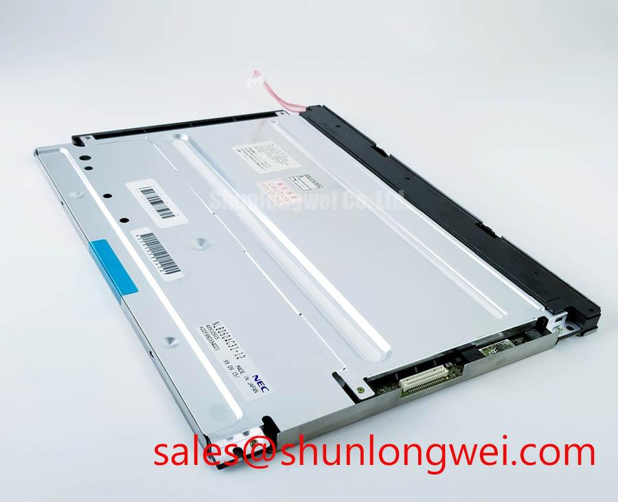
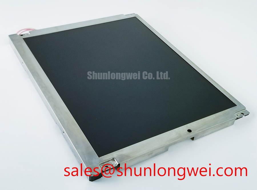
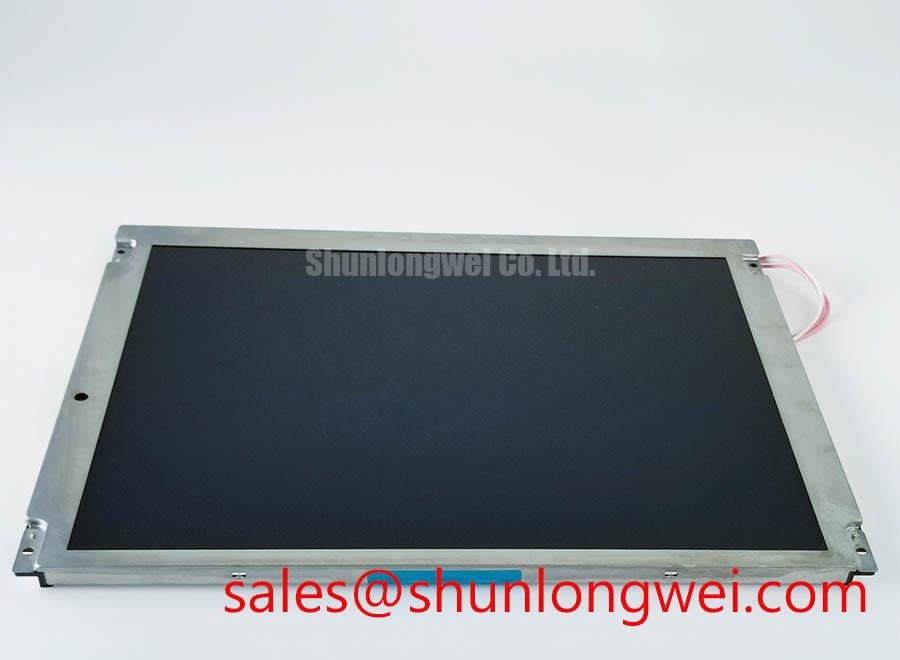
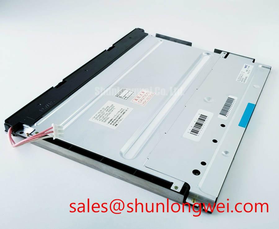
Confirm the original panel identification, inspect the TFT-LCD module and connector area, and compare the equipment documentation before applying power to a replacement NL8060AC31-12. The available product information identifies this NEC unit as an industrial LCD/HMI panel and a TFT-LCD display module. Interface voltage, signal format, backlight architecture, optical dimensions and mounting details should be confirmed against the original panel documentation before installation.
| Parameter | Product Information |
|---|---|
| Model | NL8060AC31-12 |
| Manufacturer | NEC |
| Product category | Industrial Grade LCD/HMI Panel |
| Module construction | TFT-LCD Display Module |
Backlight Inverter and Display Interface Debugging
Before connecting an inverter or display controller, trace the original panel wiring from the equipment harness to the display-side connector and identify whether the installed system uses the interface and backlight arrangement documented for this NEC unit. The supplied product data does not confirm CCFL lamp count, ignition voltage, inverter pin assignment, lamp current, LED driver compatibility or dimming behavior for NL8060AC31-12. A system integrator should therefore verify those points from the original panel documentation rather than transferring assumptions from another NEC display.
For a high-voltage substation protection or SCADA dispatch console, a blank screen can result from several conditions, including missing panel power, incorrect enable sequencing, absent video data, unsuitable backlight drive or a protection response inside the inverter. Check these conditions separately. First confirm that the equipment is isolated and that the connector keying and pin orientation match the original assembly. Next check the controller output with a known-good signal path, then inspect the panel supply and backlight enable signals in the timing relationship specified by the source equipment.
Do not use a claimed cold-ignition value as an acceptance limit for this model unless it appears in the applicable NEC documentation. The high-voltage figures sometimes associated with CCFL ignition are application-level inverter characteristics, not confirmed factory parameters for this product page. The same limitation applies to claims concerning constant-current LED conversion, PWM dimming ratios, acoustic noise or a stated backlight service life. These characteristics depend on the actual panel revision, inverter and thermal environment.
Signal integrity remains a design consideration when a replacement panel is connected through an existing controller. Keep high-speed display wiring away from inverter and switching power conductors, preserve the original return path and avoid unnecessary connector adapters. If the system uses differential video, the engineer should verify the required electrical format, pair polarity, termination and timing against the controller documentation. An oscilloscope comparison with a known-good display path is more reliable than diagnosing a dark screen from visual symptoms alone.
💡 Pro Tip: Disconnect panel and backlight cables only after the equipment power rails have fully discharged, and verify the connector orientation before reapplying power.
Full-Screen Primary Color Screening for Stuck Sub-Pixels and Background Uniformity
After the panel powers correctly, display full-screen red, green, blue, white and black test images through the original controller. This is a practical screening method for identifying persistent sub-pixel anomalies, inactive regions, uneven luminance and contamination visible through the front surface. It is not a substitute for the NEC acceptance specification, because the supplied factory data does not define pixel fault limits, luminance uniformity limits, contrast values or display inspection conditions for this model.
Inspect the surface under controlled ambient lighting before interpreting an apparent defect. A mark that changes with viewing angle or disappears when the screen content changes may involve surface reflection, contamination or optical interaction rather than a fixed pixel fault. A dark line that remains in the same location across primary colors should be documented by position and photographed under repeatable conditions. Do not attribute every line directly to a driver or bonding failure without checking the signal source, connector seating and panel mounting stress.
A 45-degree flashlight inspection can help separate surface contamination and local shadowing from image-generated defects, provided the light is used without pressing against the panel. The procedure is a general engineering recommendation, not an official test method for NL8060AC31-12. When a defect appears only with one signal format, compare the controller output, clock activity and data mapping with the original working configuration. Incorrect data order or timing can present as abnormal colors, repeated columns or unstable image content.
JEIDA and VESA mapping should not be selected by assumption. The available product information does not confirm whether this unit requires a particular LVDS mapping, TTL arrangement, bit depth or connector pinout. The system integrator should verify the required video format from the original panel documentation and controller schematic. If the replacement operates with a converted signal, validate color order, sync behavior, clock stability and image retention during cold start and warm restart conditions.
Long-term static HMI screens deserve separate attention. Fixed alarm bars, substation diagrams and status fields can create uneven ageing or temporary image retention depending on the panel technology, drive conditions and operating environment. The supplied information does not establish a burn-in rating or retention guarantee for this model. Designers should follow the original equipment maker’s display policy, use suitable screen management where permitted and verify the result on the complete assembly rather than relying on a generic LCD lifetime statement.
Thermal Management and Backlight Considerations
The product information supplied for NL8060AC31-12 identifies the unit as a TFT-LCD Display Module but does not confirm an edge-lit LED construction, a PMMA light guide, a high-nits rating, LED rail dimensions or an L70/B50 value. Those features must not be assigned to this model without the applicable factory document. If the original equipment uses a separate backlight or inverter assembly, retain the approved electrical and mechanical arrangement during replacement evaluation.
Thermal checks should begin with the complete enclosure. Confirm that ventilation openings, rear clearances, mounting brackets and nearby power components do not transfer excessive heat into the panel frame. A display that appears acceptable on a bench can behave differently inside a sealed SCADA console because heat accumulates around the rear cover and cable area. Record the enclosure temperature and panel surface condition during a representative operating cycle, then compare the result with the permitted conditions in the original equipment documentation.
Do not add an aluminium spreader rail, adhesive thermal pad or heater strip solely because a replacement panel has a similar outline. Such parts can alter mechanical stress, optical pressure and electrical isolation. Any heat-spreading solution should be evaluated as a Design Consideration with attention to contact area, insulation, clearance and service access. The final arrangement must be determined by the system engineer after checking the actual thermal path and the panel maker’s installation requirements.
Cold-environment behavior also requires documentation-led verification. LCD response, contrast perception and backlight startup can change at low ambient temperature, but the available factory data does not specify the operating range, response-time curve or heater-control requirements for this model. If a protection terminal or dispatch console is installed in an unconditioned room, perform a controlled cold-start test using the original power sequence. Check for delayed image formation, unstable backlight behavior, residual images and loss of readable status information.
The proposed same-class comparison unit NL10276BC16-06 may be reviewed as a separate sourcing reference, but similar naming or an apparently compatible size does not establish electrical, optical or mechanical interchangeability. Compare the native connector, active area, mounting pattern, signal protocol, power requirements and backlight control before considering any cross-model substitution.
Liquid Crystal Viewing Performance and Power Sequencing
For a field replacement, verify the visible image from the normal operator position as well as from the practical side and vertical angles used by the equipment. The supplied factory data does not confirm a specific viewing-angle set, dynamic contrast ratio, TN, IPS or MVA optical mode, anti-glare treatment, grayscale inversion behavior or temperature compensation curve for NL8060AC31-12. These characteristics should be taken from the original NEC documentation or measured against a known-good unit of the same configuration.
In a high-voltage substation protection or SCADA dispatch console, readability is affected by ambient reflections, protective window geometry, operator position and the rendered interface itself. Evaluate alarm colors, thin grid lines, numerical readouts and low-contrast status indicators under the actual room lighting. A panel that appears balanced on a dark bench may show glare or color shift behind a cabinet window. Surface cleaning materials should also be checked for compatibility with the installed front surface and any protective overlay.
Power sequencing should be treated as a system integration issue. Verify the order and timing of controller power, panel supply, display data and backlight enable using the original equipment behavior as the reference. White screen, image flashing or a residual image during shutdown may be associated with an incorrect sequence, a controller state or a backlight control condition; these symptoms should be isolated by measuring each signal rather than assigning a single cause. The panel documentation must determine permitted voltage levels and timing limits.
Where differential display data is used, maintain the original pair routing and reference return as far as the enclosure allows. The exact impedance, skew tolerance and clock margin are interface-specific values and are not confirmed in the supplied specification for this model. The system engineer should verify them from the transmitter and panel documentation, then confirm operation with signal measurements at the installed connector. This is especially important when an adapter board, longer cable or additional connector has been introduced.
For practical repair planning, The Ultimate Guide to Industrial TFT-LCD Technology provides broader background for reviewing interface behavior, optical selection and installation constraints. It should support engineering evaluation, while the final compatibility decision remains tied to the original panel documentation and the actual SCADA console design.