

Content last revised on October 26, 2026
NEC NL10276BC20-18F Integration and Replacement Considerations
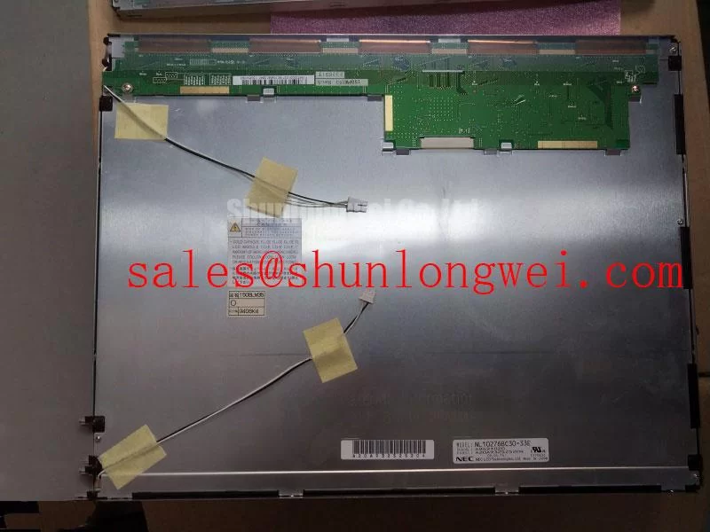
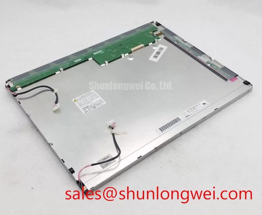
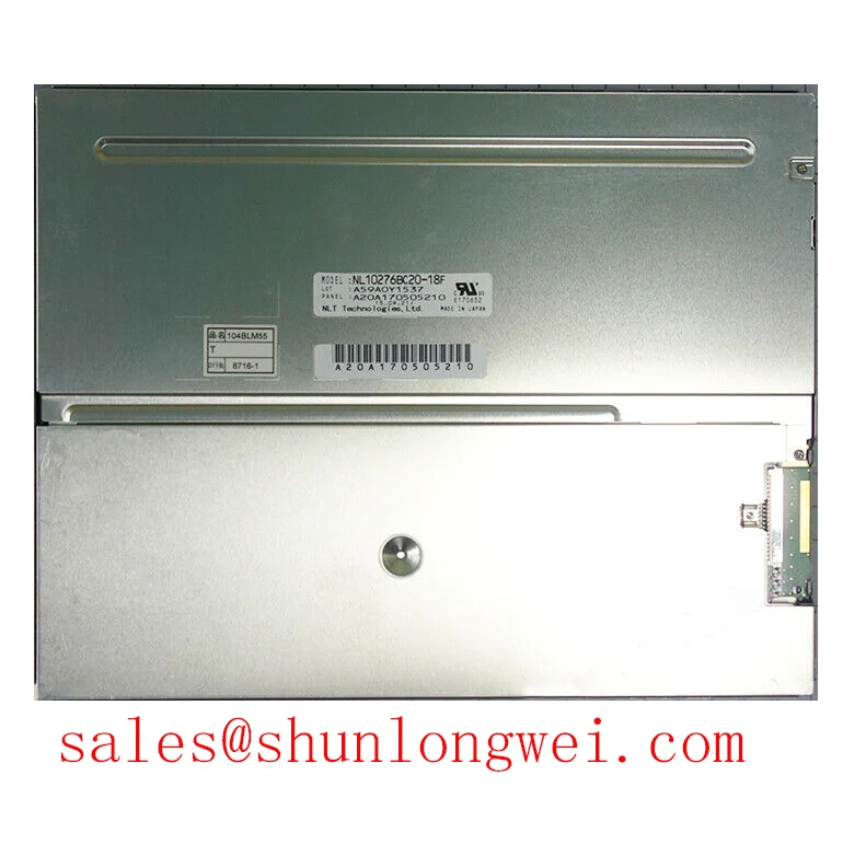
With the display assembly isolated from power, inspect the bezel contact line, mounting points, and cable restraints before disturbing the panel; uneven gasket pressure can complicate the diagnosis of dark-field patches. The NEC NL10276BC20-18F is a TFT-LCD active-matrix color display module in the industrial LCD/HMI panel category. Preserve its complete model suffix when matching the replacement request, mechanical drawing, and host display configuration.
For replacement assessment, record the existing connector orientation, mounting arrangement, and controller settings alongside the NL10276BC20-18F product reference. Specification checkpoint: consult the original NEC datasheet for numerical optical ratings, dimensions, supply requirements, interface assignment, environmental limits, and backlight characteristics. The integration guidance below is identified as Design Consideration, rather than additional factory specifications.
Assessing Symmetric Viewing Performance and Surface Glare for Multi-Angle Consoles
Compare the same grayscale pattern from the intended operator positions while keeping ambient lighting and brightness settings unchanged. As a Design Consideration, this separates angle-dependent contrast changes from reflections on the front surface. TN grayscale inversion and the wider viewing behavior associated with IPS or MVA describe different optical responses; those technology labels are not interchangeable and should not be assigned to this NEC model without its optical specification.
Use dark gradients, neutral gray, and small text to inspect readability beyond the normal viewing position. Record whether details disappear, tones reverse, or reflected light obscures the image. A nominal viewing-angle figure alone does not establish usable text contrast in the installed enclosure. Similarly, a matte appearance does not establish a particular anti-glare treatment, haze value, or outdoor readability rating.
For compatibility evaluation, an AGV or forklift telematics display would require assessment of operator sightlines, reflections, enclosure protection, and mechanical loading before accepting this panel. That application is an integration example, not a declaration of vehicle qualification. The industrial TFT display solutions resource provides useful product-family context, while the exact panel specification remains the basis for a model-level comparison.
During extended static-image checks, alternate the normal interface with neutral patterns and observe whether residual outlines change after the content changes. As a Design Consideration, reducing unnecessary persistent graphics and applying host-controlled screen blanking can support display management, but neither establishes a guaranteed image-retention limit or backlight lifetime.
Suppressing Localized Thermal Gradients and Investigating Color Shift
Map temperature differences around the enclosure edges and rear mounting structure after the display reaches a stable operating condition. As a Design Consideration, compare these observations with the locations of power electronics, restricted airflow, and mounting contacts. A localized warm region can influence optical uniformity, but yellowing or color shift should not be attributed to a particular internal material without supporting evidence.
If an enclosure heat spreader is being revised, evaluate its contact path, electrical clearance, and effect on panel mounting loads. Increasing contact pressure is not a substitute for establishing a controlled thermal path. Any added rail should avoid loading the display frame in a way that changes the visible image. Validate the assembled enclosure rather than judging performance from the panel on an open bench.
Brightness instability also warrants checking the backlight control path against the matching driver documentation. As a Design Consideration, inspect dimming behavior across the usable adjustment range and correlate visible flicker or audible noise with measured control signals. Dimming frequency, driver current, and acceptable modulation behavior belong to the verified panel-and-driver combination, not a universal setting.
Maintenance Note: Inspect ventilation paths and gasket condition during scheduled service, and reconnect display cables only after the assembly is safely de-energized. After cold storage or a substantial temperature transition, allow the assembly to reach suitable conditions before energizing it if condensation is present. Optical bonding and perimeter sealing require separate process validation; neither should be assumed to provide a hermetic barrier or a defined moisture-protection rating.
Preventing Assembly-Induced Compression and Dark-Field Mura
Inspect a dark image before installation, after initial seating, and after final enclosure assembly to identify changes associated with mounting pressure. As a Design Consideration, a patch that changes with bezel loading merits inspection of gasket overlap, frame contact, trapped wiring, and mounting alignment. It does not, by itself, identify damage to a light guide or establish a single failure mechanism.
Support the module at its designated mounting features and keep the enclosure from forcing it into alignment. Fastener selection and tightening limits should follow the applicable mechanical drawings and enclosure design. Where the mounting arrangement permits, progressive, balanced tightening can help reveal uneven seating; an assumed screw size or generic torque value is not a verified requirement for the NL10276BC20-18F.
Check that the gasket seats continuously without intruding into the active viewing area or pressing against unsupported surfaces. As a Design Consideration, sealing pressure must accommodate assembly tolerances and temperature-related movement without concentrating load on the panel. A dust seal also needs inspection at cable exits and enclosure joints, rather than only around the visible bezel.
For procurement comparisons, the NEC NL6448BC33-64 can serve as a separate comparison candidate, not an assumed equivalent. Match resolution, outline, active area, mounting locations, interface, and backlight requirements individually. Shared branding or similar model naming does not establish interchangeability.
Verifying the Differential Interface, Pixel Timing, and Power Sequence
Match the host schematic and cable drawing to the NL10276BC20-18F connector assignment before applying power. As a Design Consideration, connector appearance alone cannot establish interface compatibility. Verify signal direction, supply contacts, grounds, data assignment, and connector orientation as a complete connection map rather than inferring them from connector size.
Where the documented interface uses LVDS, compare transmitter configuration with the panel’s specified data mapping and timing requirements. Preserve differential-pair continuity through the cable and connectors, minimize discontinuities, and assess signal quality at the receiving end. Pixel-clock rate, skew allowance, termination, and sampling margins must come from the actual interface specification and host implementation.
Capture startup and shutdown behavior with the display connected under controlled test conditions. As a Design Consideration, relate the logic supply, valid image data, and backlight enable sequence to the documented timing requirements. A white screen, unstable image, or residual shutdown image can have several contributing causes; compare the captured sequence and signal behavior before changing controller settings.
Finally, inspect cable routing through the full permitted service movement. Avoid sharp bends, tension at the connector, and contact with abrasive enclosure edges; verify that the locking mechanism is fully engaged. For related enclosure and diagnostic considerations, consult Industrial Display & HMI Solutions. Retest the assembled unit after cable restraint and cover installation, because those operations can alter connector loading and routing.