Content last revised on November 3, 2026
Preventing Frame Lag & Image Smearing in Cold Storage & Outdoor Industrial Facilities
With the equipment isolated from power, inspect the display cable seating and connector latch before investigating a black screen or intermittent image on the NEC NL6448AC33-03. Record whether the fault affects illumination, image content, or both; a faint image under external illumination directs attention toward the backlight circuit, while missing graphics also requires checks at the controller and display interface.
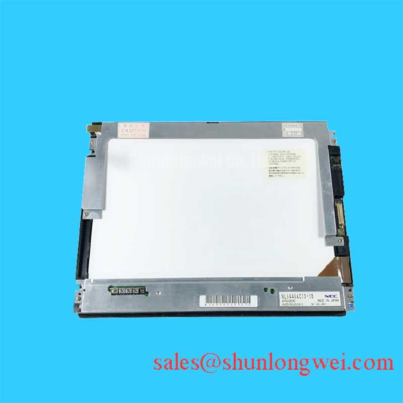
The NL6448AC33-03 is a 10.4-inch LCD display with 640 × 480 VGA resolution. Confirm its interface configuration, operating temperature limits, optical specifications, and backlight arrangement in the original model datasheet. Supply voltage, connector assignments, mechanical dimensions, and timing limits also require verification during compatibility assessment.
Compare moving edges and changing text during cold startup with the same content after the panel has warmed, keeping the module within its documented operating limits. Design Consideration: liquid crystal response generally slows as temperature falls, so image trails can develop even when the controller continues delivering frames correctly. Observe whether the whole interface updates late or whether individual transitions leave residual edges; these observations help separate controller latency from temperature dependent optical response.
The documented operating temperature range establishes the stated temperature boundary, but it does not establish a gray-to-gray response time at every temperature. Evaluate transitions representative of the actual interface rather than relying only on a moving white cursor. Dark text, shaded backgrounds, and status indicators can expose different transition behavior. Compare controller output timing during the same test so optical smearing is not confused with an irregular frame stream.
If the host supports display compensation, designers should evaluate its effect on overshoot, text readability, and startup behavior before changing production settings. A heater is a system accessory requiring its own thermal control assessment, rather than an assumed part of this module. Measure temperature near the mounted display and examine gradients across the enclosure before deciding whether additional heating is appropriate.
Backlight flicker requires a separate observation from motion smearing. Engineering Recommendation: when the installed driver uses PWM dimming, inspect its current waveform across the intended brightness adjustment range and compare it with visible flicker or audible noise. Frequency, minimum pulse behavior, and duty cycle linearity depend on the driver and system implementation; changing a setting without checking optical output can conceal unstable low brightness operation.
Thermal evaluation should remain within the documented operating boundary, including enclosure heat rise. Inspect perimeter condition and mounting alignment after representative temperature exposure without assuming a particular sealant chemistry or cycling qualification. For broader test planning, The Ultimate Guide to Industrial TFT LCD Technology provides supporting integration context rather than a substitute for model specific limits.
Preventing Localized Light Guide Plate (LGP) Compression Warp on Dark Screen Fields
Display a uniform dark field and compare any bright patches or uneven shading before and after the panel is secured in its enclosure. A change associated with fastening can indicate assembly stress, although optical nonuniformity alone does not identify the affected internal layer. Keep the diagnostic focus on bezel contact, mounting alignment, and cable loading before attributing the symptom to the light guide plate.
Design Consideration: the enclosure should locate the module through its intended mounting features while avoiding pressure on the viewing surface. Check that the bezel does not bear unevenly against the display and that mounting points sit without forced alignment. Use the applicable assembly drawing to establish screw engagement and tightening requirements; a generic fastener torque does not establish a safe limit for this particular module.
Assess fit at the relevant enclosure temperatures because surrounding structures can expand differently. Clearance that appears adequate on a workbench may change after the equipment reaches operating temperature. If optical shading changes with temperature or mounting condition, record its location and repeat the comparison under controlled conditions. Avoid adjusting fasteners while the equipment is energized.
Cable routing also affects mechanical loading. Support the harness so connector retention does not carry its weight or absorb enclosure movement. Where flexible circuitry is present in the assembly, avoid creases, twisting, and repeated bending at the connector exit. Bend allowance and movement requirements belong to the actual cable specification; connector security should be checked after representative equipment movement.
For persistent outlines from static graphics, compare a neutral image after changing the displayed content and allowing recovery. Image retention can have several contributing conditions and should not immediately be classified as permanent damage. Designers should evaluate screen blanking, content movement, or interface changes against operating needs, then verify readability and retention behavior on the assembled equipment.
Optical Luminance Degradation Curve & CCFL-to-LED Modernization Retrofit Pathways
Measure luminance under repeatable brightness settings and thermal conditions before deciding that a dim screen requires replacement. The datasheet luminance specification is an optical reference under its stated measurement conditions, while a field measurement also reflects driver operation, surface condition, measurement geometry, and operating temperature. Comparing readings taken under different conditions can make a power problem resemble gradual backlight deterioration.
Verify the installed backlight arrangement and its service requirements before selecting replacement parts. A service assessment should examine the installed backlight driver, its enable signal, dimming command, and output behavior. If illumination changes with brightness commands or enclosure temperature, correlate those changes with electrical measurements before assigning the fault to the backlight assembly.
Engineering Recommendation: inspect supply stability at the driver input while the fault is present, then check whether commanded brightness corresponds to consistent illumination. Driver protection, interrupted connections, and deteriorating light output can produce overlapping symptoms. Measurements should establish which part of the illumination path changes when the symptom appears.
A CCFL-to-LED conversion requires assessment of the driver, wiring, enable polarity, dimming control, mechanical clearance, and thermal behavior. A shared screen size does not establish compatibility between illumination systems, and serviceable backlight construction does not by itself establish a universal retrofit interface.
Keep luminance maintenance separate from reliability terminology: a reduction in light output and MTBF describe different characteristics. No service interval follows directly from serviceable construction. For broader manufacturer context on industrial display technologies, consult Tianma Industrial Display Products; assessment of an individual replacement still depends on its electrical and mechanical specifications.
Digital RGB Bus Synchronization & Logic Power Rail Verification
Match the controller wiring to the interface specified in the original NL6448AC33-03 datasheet before applying power. Where an interface uses six bits per color, it carries 18 RGB data bits; a 24-bit RGB connection must not be assumed compatible. Establish connector orientation, signal assignments, grounds, logic levels, and timing requirements from the panel and host drawings before assessing a replacement cable.
⚠️ Field Alert: Isolate power and allow the equipment supplies to discharge before disconnecting or reseating display and backlight connectors.
For a split image, unstable picture, or incorrect colors, compare pixel clock, synchronization, and color data at the receiving connector with the controller configuration. Check continuity and connector engagement with power removed, then examine signals using suitable probes. Incorrect data assignment and marginal timing can produce similar visible faults, so an image symptom alone should not determine the repair.
Design Consideration: verify supply behavior and signal sequencing against the original timing requirements, including startup, shutdown, and interrupted power recovery. For a parallel RGB connection, LVDS differential routing assumptions and JEIDA/VESA mapping do not establish compatibility. Assess ringing and timing at the receiver under actual harness conditions.
When comparing the NL6448AC33-03 with another display such as the NL10276AC30-53D, compare resolution, interface, connector assignment, mounting envelope, and backlight requirements individually. For a railway passenger information terminal or cab signalling display assessment, include the host’s environmental and approval requirements. After installation, verify stable text, color patterns, startup recovery, and brightness control with the production harness secured.