

Content last revised on November 9, 2026
VESA vs. JEIDA Data Mapping Alignment & Even/Odd Channel Signal Integrity
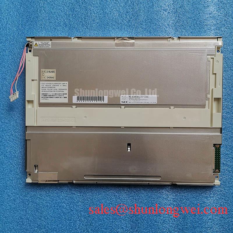
I compare the controller schematic, panel connector assignment, and cable continuity before applying power to an NEC NL8060BC31-28E with a split image or incorrect colors. Confirm the documented interface before connecting a controller; LVDS and TTL signaling are not interchangeable. Supply voltage, connector pinout, implemented signaling format, channel arrangement, timing limits, operating temperature, and backlight specifications require the original panel datasheet.
Design Consideration: Establish the actual signal path before changing controller settings. LVDS carries serialized differential signals; TTL uses parallel logic signals with different electrical requirements. For an LVDS implementation, compare transmitter bit assignments with the panel receiver mapping. VESA and JEIDA selections matter only where the documented receiver supports those arrangements. Likewise, investigate even/odd pixel assignment only if the documented architecture divides pixels between channels.
Use solid primary colors, grayscale ramps, and alternating pixel patterns to distinguish bit-assignment errors from timing instability. Incorrect color significance can produce repeatable tonal errors, while marginal sampling can produce intermittent corruption. Neither observation alone identifies the failed part. Compare the image behavior with clock and data measurements at accessible receiver-side test points, using probes that do not materially load the interface.
Engineering Recommendation: Compare supply rise, reset release, valid video, and backlight enable against the specified sequence. Assess transmitter jitter and receiver setup and hold margins over the intended temperature range rather than importing timing values from another panel. Pro Tip: Preserve differential-pair symmetry through connectors and cable transitions, and validate receiver timing before treating a clean-looking clock trace as proof of interface compatibility.
For replacement screening, compare NL6448AC30-10 documentation independently; a related NEC model number does not establish matching resolution, mounting geometry, or electrical compatibility. Record each difference before considering an adapter or controller change.
Preventing Frame Lag & Image Smearing in Cryogenic Storage & Outdoor Industrial Facilities
Display a moving edge beside a stationary reference while tracking panel temperature to separate liquid-crystal response changes from controller buffering. Design Consideration: Lower temperature can slow liquid-crystal transitions, but visible trailing is not automatically evidence of an interface fault. Compare cold-start behavior with stabilized operation using the same image sequence, backlight setting, and controller configuration.
Capture the source video timing alongside an optical response measurement where suitable equipment is available. A delayed complete frame suggests a different investigation from a transition that begins promptly but settles slowly. Gray-to-gray behavior also depends on the starting and ending levels; a single black-to-white observation cannot characterize every moving image. Compensation settings should follow the controller and panel capabilities rather than an assumed universal adjustment.
Keep environmental testing within documented panel limits. A proposed enclosure temperature cycle is a system qualification condition, not an operating rating for this NEC display. Watch for condensation during transitions and compare image uniformity before and after thermal stabilization. Edge discoloration, intermittent connections, and persistent image changes require separate examination rather than attribution to an assumed sealant composition.
When evaluating an AGV or forklift telematics display replacement, assess enclosure temperature, vibration exposure, readability, and controller compatibility together; these are potential integration contexts, not established qualifications of this panel. The broader discussion in A Clear Advantage for Industrial Displays provides display-technology context, not an environmental acceptance standard for the NL8060BC31-28E.
For electrically noisy installations, assess cable return paths, connector continuity, and differential balance while operating nearby switching loads. Set impedance and skew acceptance criteria from the actual transmitter, receiver, and interconnect requirements. A room-temperature image test alone does not establish timing margin at environmental extremes.
Flush-Mount Open-Frame Bezel Integration & Perimeter Gasket Shock Isolation
Measure the module envelope, active-area position, mounting features, and connector clearance before releasing a flush-mount bezel drawing. The 12.1 inch diagonal describes the display size, not the enclosure cutout. Build the tolerance stack around the mechanical drawing and actual assembly datums, including cable bend clearance and access for connector engagement.
Design Consideration: Transfer enclosure loads through documented mounting locations rather than the display surface. A perimeter gasket should accommodate the assembly stack without imposing uneven pressure on the module. Select its compression behavior against the enclosure design and environmental requirements; do not assume a particular gasket material or compression target is specified for this panel.
Compare uniform dark and mid-gray images before mounting, after initial fastening, and after final enclosure closure. A pressure-dependent change in brightness uniformity can help locate mechanical loading, but it does not uniquely identify an internal optical defect. Check bezel flatness, trapped cables, bracket alignment, and gasket interference before increasing fastener preload.
Use fastener size, engagement, tightening sequence, and torque limits appropriate to the documented mounting arrangement. During vibration evaluation, support the cable harness independently so connector loads do not become a substitute for strain relief. Record image interruptions and connector movement together, then inspect the corresponding mechanical interface.
Diffuser Film & Prism Sheet Thermal Buckling Prevention under Continuous Full-Duty Operation
Map enclosure and module-edge temperatures at stabilized brightness before adding heat-spreader rails or changing ventilation. Design Consideration: Uneven heating and constrained expansion can affect optical uniformity, but that mechanism does not establish the internal film arrangement or light-guide material of the NL8060BC31-28E. Keep thermal modifications outside the optical stack and evaluate whether added brackets introduce pressure.
Backlight power assessment starts with the specified source and its driver requirements. Where an external constant-current driver is applicable, evaluate regulation, conversion losses, enable behavior, and fault recovery as system characteristics. The related NL8060AC31-12 is a separate display reference, not evidence of a compatible backlight driver or shared power topology.
For a dimming interface that supports PWM, assess luminance stability, low-brightness behavior, camera banding, and audible noise across the intended adjustment range. Frequency, duty-cycle limits, and polarity belong to the documented driver interface. Observe dimming behavior alongside supply ripple and image stability to distinguish backlight modulation from video-path disruption.
The Tianma industrial-display resource provides industrial-display portfolio context. Product-specific thermal and backlight limits remain separate from general technology descriptions.
During driver fault evaluation, monitor documented fault outputs and output transients using the driver supplier’s approved procedure. Do not create open-circuit or short-circuit conditions on an energized panel as an exploratory test. Record protection recovery and post-test luminance separately; neither demonstrates a quantified service life or an LED lumen-maintenance rating.