

Content last revised on September 14, 2026
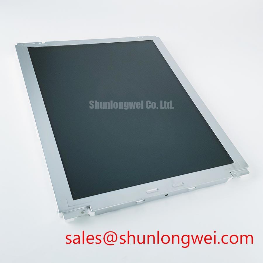
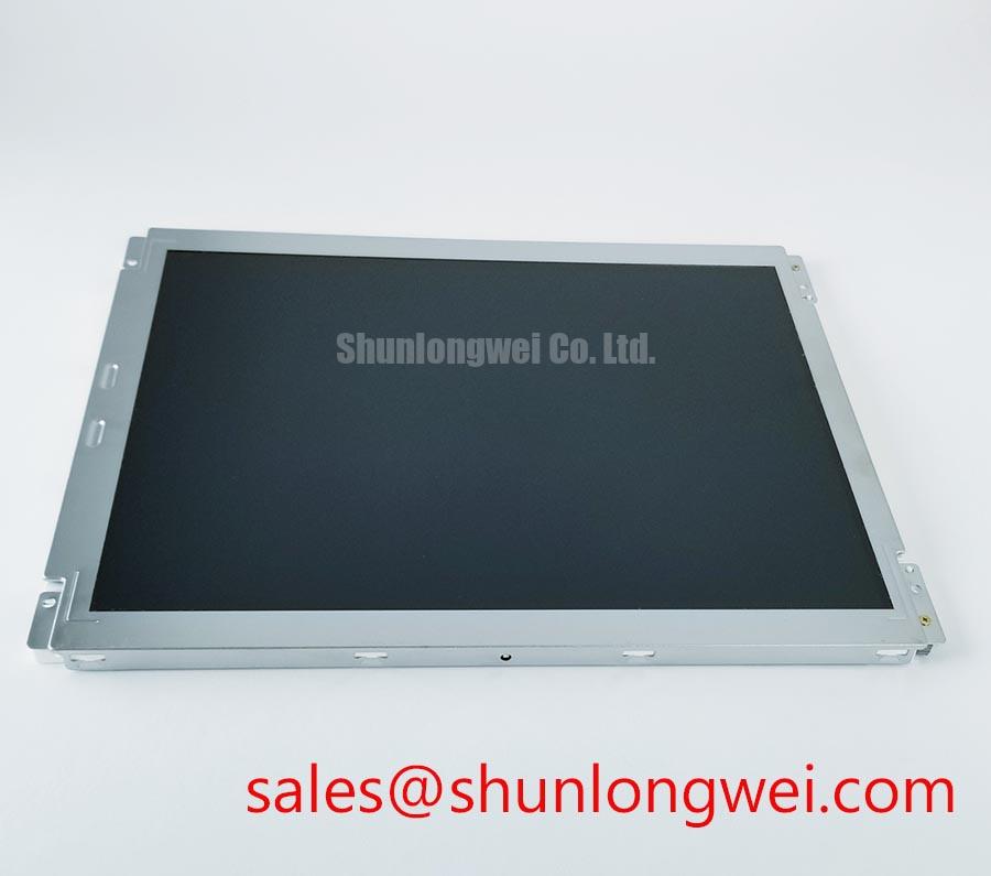
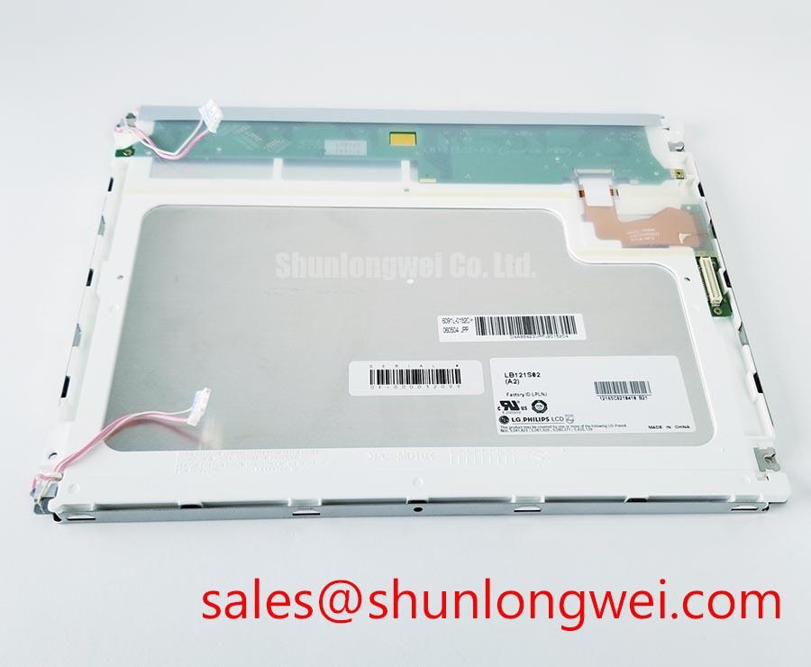
LG Display LB121S02-A2 Industrial Grade LCD HMI Panel
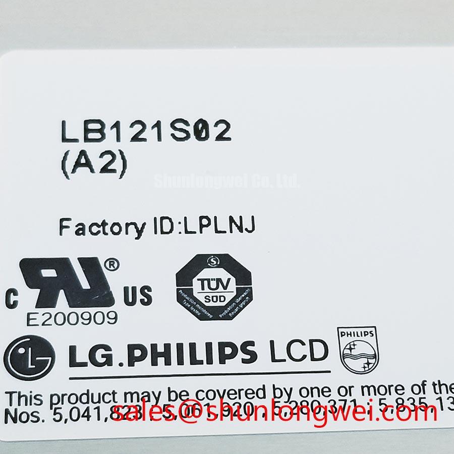
Start a replacement check by comparing the installed panel label, connector position, mounting pattern, and visible glass condition with the candidate LB121S02-A2. The supplied factory information identifies this unit as an LG Display Industrial Grade LCD/HMI Panel in a TFT LCD Display Module package, with its specification status recorded as Official Factory Spec Verified. Resolution, active area, interface, supply voltage, backlight type, luminance, viewing angle, and mechanical envelope should be confirmed against the original panel documentation before installation.
| Parameter | Available product information |
|---|---|
| Model | LB121S02-A2 |
| Manufacturer | LG Display |
| Product category | Industrial Grade LCD/HMI Panel |
| Package or enclosure type | TFT LCD Display Module |
| Specification status | Official Factory Spec Verified |
This information is sufficient to identify the product category and manufacturer, but it does not establish electrical or optical compatibility with every 12.1 inch industrial display position. A maintenance engineer should compare the original service documentation for connector pinout, signal standard, power sequencing, panel timing, backlight drive requirements, control signals, mounting dimensions, and bezel clearance. The system integrator should verify the required supply voltage from the original panel documentation rather than assuming compatibility from the model designation alone.
Micro Twist Mechanical Stress Fracture Prevention on the Glass Display Assembly
Before removing a working display, record the symptom with the machine in its normal operating state. Check whether the defect follows the image content, remains fixed at one location, changes with viewing angle, or appears only after the panel is installed in the chassis. These observations help separate a panel image fault from cable routing, controller, or enclosure stress without assigning a single cause prematurely.
A practical bench check uses primary red, green, and blue screens together with black and white fields. Inspect the panel directly and then use a flashlight held at approximately 45 degrees to examine dark areas and edge transitions. A backlight irregularity often remains related to illumination distribution, while a driver or glass connection defect may track a line, column, or fixed region of the image. This test is only a screening method. Verify suspected signal path problems against a known good controller and inspect the flexible cable for contamination, uneven seating, or excessive bend.
Mechanical stress is best assessed after the display has been removed from the enclosure. Look for chassis distortion, concentrated contact points, cable tension, and fasteners that pull one side of the frame more tightly than the other. The external package information supplied for this model confirms a TFT LCD Display Module, but it does not document a particular internal bonding construction or driver bump arrangement. Therefore, the maintenance record should describe the observed symptom and physical conditions rather than attributing the defect to an unverified internal structure.
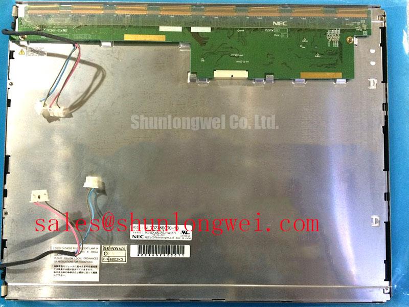
When a replacement is being evaluated for a CNC operator panel or robot teach pendant, compare the original panel’s image orientation, connector access, cable bend path, and front surface position. The model NL10276BC30-18 may be reviewed as a separate same class reference during a compatibility study, but its use is not a blanket substitution recommendation for the LB121S02-A2. Electrical timing and mechanical fit remain system determined.
Thermal Spreader Placement Along Narrow Display Edges
Inspect the enclosure airflow before adding any thermal hardware. Dust accumulation around vents, blocked cabinet filters, compressed sealing material, or a cable pressed against the rear of the module can alter the local temperature distribution. A narrow aluminum rail can sometimes help spread heat away from a concentrated enclosure contact area, but it should not be treated as an officially specified accessory for the LB121S02-A2.
Any heat spreader must be mechanically isolated from the active display area and positioned so that it does not load the glass, obstruct the backlight assembly, pinch flexible cables, or create a new pressure point. The interface should be continuous enough for the intended thermal path while preserving the clearance defined by the original chassis. The correct material, thickness, contact area, and attachment method are design considerations that require measurement of the actual enclosure and thermal test results.
Do not infer LED backlight lifetime, L70 performance, B50 behavior, MTBF, or brightness decay from the model number alone. No such values are included in the supplied official parameter set. If the original documentation provides a backlight lifetime curve, evaluate it with the actual current control, ambient temperature, duty cycle, and cabinet airflow. Without that source, a service team should document brightness uniformity and temperature trends during controlled operation rather than publish a numerical life prediction.
Thermal troubleshooting should begin with a visual inspection, followed by measurement at representative operating conditions. Compare the center and edge image appearance, check whether the fault changes after the cabinet reaches thermal equilibrium, and verify that the display controller is delivering the expected signal. If the panel is installed behind a sealing gasket, inspect compression uniformity around the entire perimeter. A gasket that has hardened, shifted, or folded can affect both heat transfer and mechanical loading.
For broader enclosure, sealing, airflow, and operator interface planning, the Industrial Display & HMI Solutions reference provides a useful system level context. It should complement, not replace, the original LG Display documentation for this model.
Chassis Fastener Loading and Optical Mura Prevention
Measure the chassis opening and mounting points before transferring the panel. The supplied product data does not include an outer bezel drawing, mounting hole dimensions, fastener specification, or permitted chassis torque for the LB121S02-A2. Those values must come from the applicable mechanical drawing or the equipment manufacturer. A CNC operator panel and a robot teach pendant may use different carrier plates even when the display category appears similar.
During installation, clean the mating surfaces and confirm that the module rests on its intended support points rather than on a corner, cable, label, or uneven gasket. Tighten the enclosure in a gradual cross pattern only when the equipment drawing defines a suitable fastener method. The objective is even retention without bending the frame. Any torque value copied from a different panel, bezel, or fastener size should be treated as a general design consideration, not as an LB121S02-A2 factory specification.
After installation, run black, white, and mid level gray fields while checking the panel from the normal operator position and from oblique angles. Record whether bright or dark patches appear only after fastening. Optical mura can be influenced by enclosure pressure, optical stack condition, backlight uniformity, viewing angle, ambient reflections, and signal processing. A repeatable change between loose and secured states warrants mechanical review before replacing the controller.
Do not publish a contrast ratio, sunlight performance value, anti glare treatment, or surface coating description for this model unless it is confirmed in the original LG Display data. The supplied factory information identifies the module and category but does not provide a verified contrast ratio at a specified illuminance or confirm a particular anti glare etching process. Under strong ambient light, designers should evaluate hood geometry, surface reflections, operator viewing position, and the complete front window assembly as part of the equipment design.
Maintenance Note: Isolate power before disconnecting the display cable, and inspect the cooling path and perimeter gasket during every scheduled cabinet service.
Normally White TN Compatibility and Viewing Direction Verification
Panel technology, grayscale behavior, viewing direction, and viewing cone are not included in the supplied LB121S02-A2 factory parameter set. Do not classify this unit as TN, IPS, or MVA from a product photograph or from a replacement listing. The integrator should verify the original panel documentation for display mode, image orientation, grayscale response, viewing angle, polarizer direction, and any controller settings that affect the image.
For a field replacement, display a grayscale ramp and several neutral gray blocks while the operator views the screen from the actual standing or handheld position. Move the panel through the expected vertical and horizontal angles and note inversion, contrast change, color shift, or loss of detail. This procedure is especially important when a panel is used in a CNC operator interface or robot teach pendant, because the viewing position can change substantially during operation.
If grayscale inversion or an unusual tonal shift is observed, confirm the panel orientation and controller timing first. Check the original signal path, cable seating, image rotation settings, and any configuration stored in the host equipment. Do not correct an uncertain panel mismatch by changing drive voltage or timing values without the original panel specification and a controlled validation plan.
Surface readability under high illumination should be evaluated with the complete assembly installed, including the protective window, gasket, bezel, and operator controls. An anti glare claim cannot be assigned to the LB121S02-A2 without a documented source. Reflections may be reduced through enclosure geometry and viewing direction, but these are system level design measures rather than guaranteed characteristics of the display module.
Where the display is installed near circuits with elevated voltage or exposed conductive structures, the completed equipment requires its own insulation coordination review. General principles associated with Insulation Coordination under IEC 60664 should be considered by the responsible equipment designer; they do not constitute a product certification for this LCD module. Verify creepage, clearance, protective barriers, grounding, and the enclosure construction against the applicable equipment standard.