




Content last revised on September 10, 2026
Display Interface Synchronization and Logic Power Rail Verification
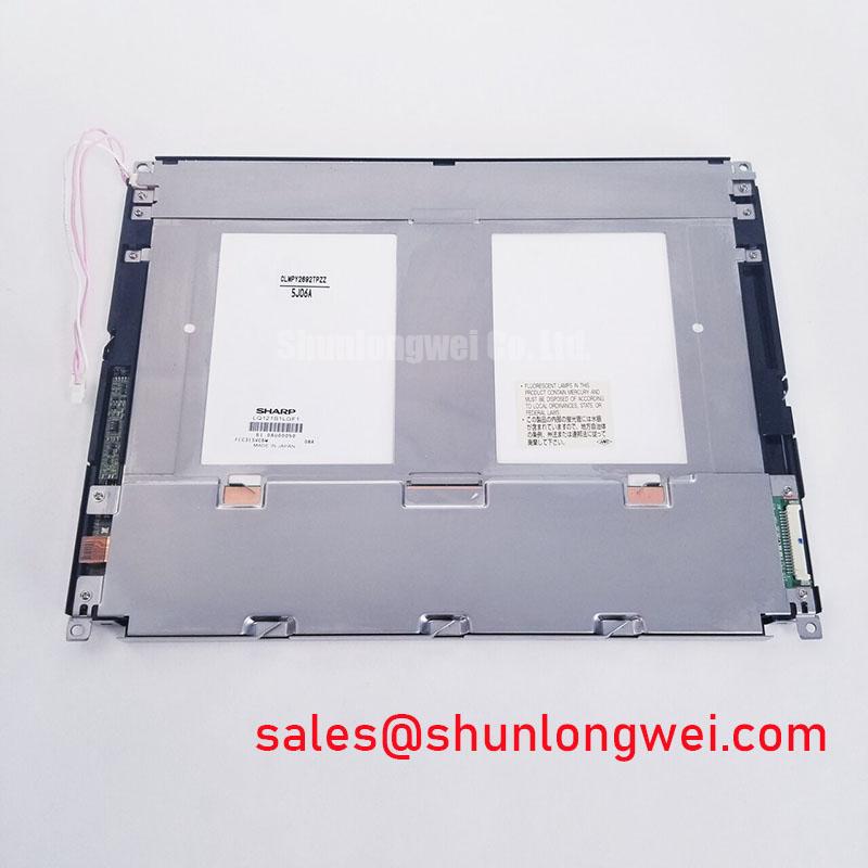
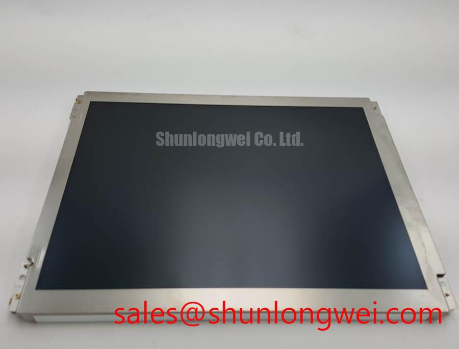
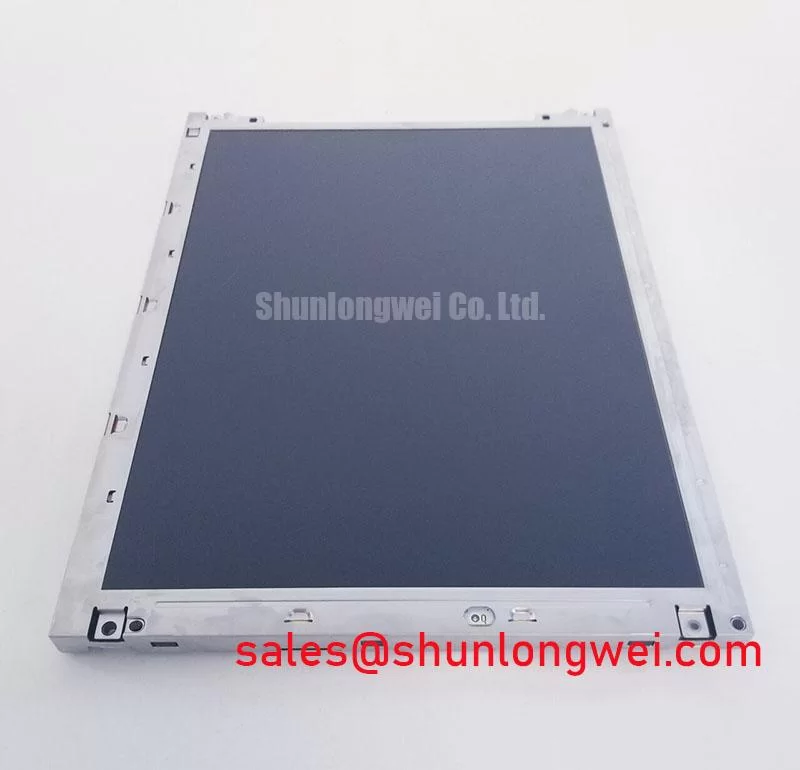
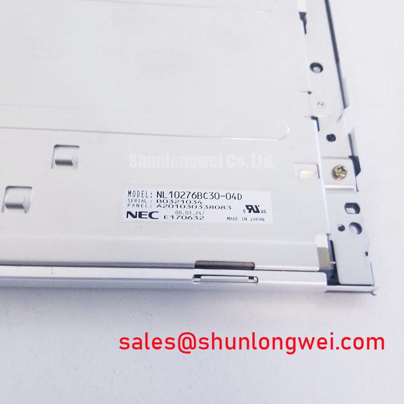
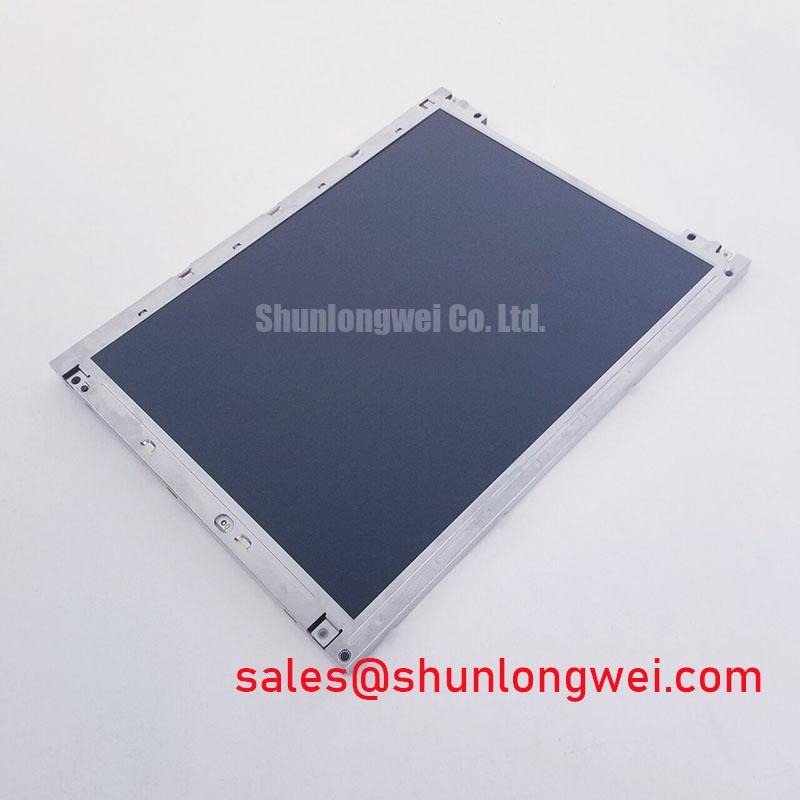
Start at the isolated panel assembly: inspect the label, connector seating, flex cable alignment, and visible glass or bezel damage before applying power. The NEC NL10276BC30-04D is identified in the supplied factory information as an Industrial Grade LCD/HMI Panel using a TFT LCD Display Module package. Its specification status is recorded as Official Factory Spec Verified. The available factory data does not establish the display resolution, active area, interface pinout, logic voltage, backlight type, viewing angle, contrast ratio, or environmental rating, so those items should be confirmed against the original panel documentation before installation.
This distinction matters during an urgent replacement. A mechanically similar industrial LCD can still fail to start if its signal mapping, power rail, backlight circuit, or connector orientation differs from the installed unit. The NEC model should therefore be evaluated as a complete display replacement at the equipment interface, not by appearance alone. For a petrochemical operator station or field monitoring terminal, the surrounding enclosure, cable routing, sealing method, and certified system construction remain the responsibility of the equipment designer.
Display Interface Synchronization and Logic Power Rail Verification
Begin the electrical check with the host controller disconnected from the replacement display. Identify the original panel documentation and confirm the logic supply rail, enable signals, ground reference, pixel clock, synchronization signals, and data ordering. Do not assume a 3.3 V or 5 V rail from the model number or connector appearance. The system integrator should verify the required supply voltage from the original NEC panel documentation and compare it with the host board output under load.
Power sequencing deserves attention when a display shows a white field, intermittent startup, residual image, or an unstable first frame. Use an oscilloscope to observe the logic rail, display enable signal, clock activity, and RGB data at the panel connector during startup and shutdown. The correct sequence is system determined unless it is explicitly stated in the applicable factory documentation. Check whether the host keeps the interface inactive until the panel rail is stable, and verify that shutdown does not leave signal activity present after the display supply has collapsed.
If the panel uses a 24 bit TTL RGB interface, each color channel and synchronization line must be traced according to the documented pin assignment. A swapped color group, incorrect bit order, or incompatible JEIDA and VESA style mapping can produce split images, unusual colors, diagonal noise, or a stable white screen. These symptoms are not sufficient to identify one fault by themselves. Compare the suspect assembly with a known good signal path and confirm the data map from the original system drawings.
High speed digital routing is also a system design consideration. Keep the clock and data return paths controlled, avoid unnecessary stubs, and maintain consistent reference planes where the host board permits. A nominal cable impedance or routing target should not be presented as an official characteristic of this NEC display without a supporting datasheet. The designer should validate signal integrity at the panel connector, especially where a long harness passes through a hinged operator door or a sealed enclosure.
Brightness control must be checked separately from image data. If the host uses PWM or a dedicated backlight control input, confirm that the control method is compatible with the installed display assembly. Do not transfer a frequency or duty cycle requirement from another panel family to the NL10276BC30-04D without documentation. During commissioning, observe visible flicker, audible interaction from the backlight circuit, and brightness changes at low command levels. The final control range is determined by the display and its driver architecture.
For selection work, compare the complete interface record rather than only the model dimensions. The related NL10276BC16-06 may be reviewed as a separate product record, but compatibility must be established from its own documented electrical and mechanical specifications.
Backlight Inverter Operation and Ignition Debugging
Do not connect an unknown backlight inverter to the replacement panel while the assembly is open on a workbench. First identify whether the original equipment uses a CCFL inverter, an LED driver, or another backlight arrangement from the panel documentation and the host power board. The supplied factory information for the NEC NL10276BC30-04D identifies the product as a TFT LCD display module but does not confirm a CCFL lamp count, inverter topology, striking voltage, lamp current, LED configuration, dimming method, or backlight service life.
When the original system uses a high voltage inverter, inspect the lamp leads, insulation, connector housings, transformer area, and current feedback path with the equipment isolated. A failed lamp, open connector, inverter protection event, or unstable supply can all create a dark screen while the digital image remains active. High voltage probing should be performed only with equipment rated for the circuit and by personnel qualified for the hazard. The inverter output must not be inferred from a generic CCFL value or from another NEC display family.
If the system has been modified to use an LED driver, treat that driver as a separate electrical subsystem. The required forward voltage, current regulation, enable logic, dimming input, and fault response must be verified from the driver documentation. A constant current LED output should not be connected to an unconfirmed panel backlight input. Likewise, a controller configured for PWM dimming may behave incorrectly if the replacement assembly expects an analog level or a different enable convention.
During a controlled bench test, measure the host supply at the driver input while monitoring the backlight enable command. If the enable command is present but illumination does not start, inspect the driver protection status and connector continuity before concluding that the LCD itself is defective. If illumination starts and then drops out, compare current feedback behavior with the known good assembly. Record the test conditions, because brightness changes caused by enclosure temperature, supply loading, or protection thresholds can otherwise be mistaken for a panel fault.
Ambient light also affects practical readability. The supplied data does not verify a contrast ratio under direct sunlight, an anti glare treatment, or a specified 50,000 lux performance level for this model. For a Zone 2 explosion proof operator station, the integrator should evaluate the complete window, bezel, viewing direction, enclosure lighting, and certified construction. A display module alone cannot establish the EMC, hazardous area, optical, or safety compliance of the finished operator station.
⚠️ Field Alert: Disconnect power and allow the inverter section to discharge before removing the display cable or backlight connector, then verify the absence of hazardous voltage with an appropriate meter.
Polarizer Durability and Optical Retardation Film Inspection under Direct Industrial Lighting
Inspect the front surface before fitting the panel into the operator station. Use a clean, non abrasive inspection method to look for scratches, pressure marks, cloudy areas, edge lifting, contamination, and uneven reflections. Do not press the active area while checking a suspected defect. The supplied official information does not specify the polarizer construction, optical retardation film, anti glare process, panel cell mode, viewing angle, or temperature response of the NL10276BC30-04D.
Viewing performance should be assessed with the display installed in its intended mechanical position. Check the normal operator line of sight, oblique viewing from each practical direction, and the effect of overhead lighting or sunlight entering through a window. TN, IPS, MVA, and other LCD modes can show different grayscale and color behavior, but the mode of this particular NEC model must not be guessed from the product category. If wide angle performance is required, the system designer should verify the measured viewing specification from the original panel documentation.
For industrial HMI use, long static screens require an operating policy based on the complete display system. Fixed menus, alarm banners, and process diagrams can produce temporary image retention depending on panel technology, temperature, drive conditions, and display content. Avoid treating a persistent image as proof of one internal failure without comparing it with a uniform color test and a known good panel. Where the equipment permits, use screen rotation or controlled content variation as a design consideration, subject to the process and safety requirements of the host system.
Temperature testing should be performed on the assembled product rather than on the loose display alone. Cold conditions can alter liquid crystal response, startup behavior, cable flexibility, and backlight output. The available factory data does not provide a verified operating temperature range or a heater requirement for this model. If the enclosure includes a heater strip, the integrator should control it according to the enclosure design and confirm that the panel reaches a stable condition without creating condensation or localized optical stress.
Optical bonding, sealing, and dust control are also enclosure level decisions. A replacement TFT LCD module should be installed using the original frame, gasket arrangement, pressure distribution, and approved sealing process where applicable. Do not claim that the display module itself provides gas tightness, explosion protection, or a certified environmental barrier. For technical background on panel construction, interface selection, and common integration misconceptions, consult The Ultimate Guide to Industrial TFT LCD Technology.
Flashlight Dark Shadow Optical Diagnostic to Isolate Logic and Backlight Faults
When the HMI is dark, first confirm the host supply and then perform a controlled image test. Apply a primary color sequence from the controller, such as red, green, blue, white, and black, while observing the panel from the normal viewing position. The purpose is to determine whether image data is reaching the LCD and whether illumination is operating. A dark screen alone cannot distinguish between a disabled backlight, missing logic power, absent timing signals, connector contact trouble, or a panel level fault.
After the primary color check, place a flashlight at approximately a 45 degree angle to the front surface and inspect for a faint image without pressing the panel. A visible shadow or faint color transition can suggest that the LCD is receiving some image information while the backlight path requires further testing. No visible image does not prove that the logic section has failed, because viewing angle, ambient reflections, controller state, and signal timing can affect the observation. Verify the result with voltage measurements and an oscilloscope comparison against the known good signal path.
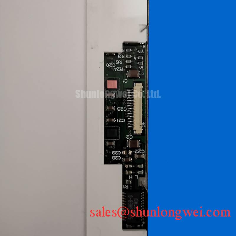
Inspect the flexible cable and connector under magnification. Check that the cable is fully inserted, the locking mechanism is engaged, contacts are clean, and the bend path does not place force on the connector. The correct bend radius and mechanical retention are determined by the original cable and equipment construction; do not impose a generic flex life value on this NEC module without a manufacturer specification. In a hinged panel door, provide strain relief through the system mechanics rather than allowing the display connector to carry cable movement.
Line defects, uneven columns, flickering regions, or a fixed band should be documented by location, temperature, viewing angle, and cable movement. These observations may indicate an interface connection problem or a panel level defect, but they are not a single cause diagnosis. Avoid flexing the glass or pressing the bonded edge to make a fault disappear. Such handling can convert an intermittent service symptom into permanent damage and does not provide a reliable repair method.
For a suspected backlight fault, repeat the test with the host brightness command, enable state, driver input, and driver protection feedback recorded. For a suspected logic fault, record the panel rail, ground reference, clock presence, synchronization activity, and RGB data behavior. The replacement decision should be based on the complete evidence set and the original equipment documentation. The NEC NL10276BC30-04D remains an industrial TFT LCD display module with the supplied factory identity and category; all unverified interface and environmental characteristics require confirmation before system release.