



Content last revised on September 10, 2026
Controlled 100 Ohm Differential Impedance Flex Routing to Suppress High Frequency Jitter
| Model | LB121S1-A2 |
|---|---|
| Manufacturer | LG Display |
| Product Category | Industrial Grade LCD/HMI Panel |
| Display Technology | TFT LCD Active Matrix Color Display Module |
| Specification Status | Official Factory Spec Verified |
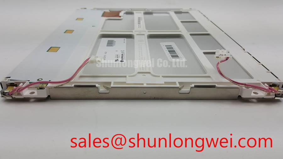
Probe the panel supply rail, differential clock pair, and data pair activity at the display connector before replacing the LB121S1-A2 in a machine with split images, unstable vertical edges, or intermittent pixel timing errors. The panel is an LG Display TFT LCD Active Matrix Color Display Module, and its interface condition must be assessed at the connector rather than inferred from the symptom seen on screen.
A controlled 100 Ohm differential impedance path is a Design Consideration for high speed display signalling where a differential video interface is used by the host system. Cable routing, connector contact quality, shield continuity, and return path integrity can all affect eye opening at the receiving end. Oscilloscope comparison against a known good channel helps identify whether the clock waveform has excessive ringing, amplitude variation, timing instability, or common mode disturbance.
Power sequencing also deserves attention during replacement work. The logic supply requirement, rise time, enable relationship, and video source timing must be verified from the original machine documentation and panel interface record. The LB121S1-A2 should not be connected to a host solely because its physical size appears similar. Incorrect logic rail selection or an unmatched signal mapping can cause a blank image, color distortion, repeated image fragments, or permanent communication failure between the controller and panel.
JEIDA and VESA data mapping require particular care where an existing controller board has been repaired, substituted, or reconfigured. A correct clock can still produce incorrect color order or divided image zones if bit assignment does not match the panel expectation. Engineering Recommendation: inspect the original harness pinout, controller output format, and panel connector orientation as one electrical chain. The panel connector, cable labeling, and controller documentation should agree before the system is powered.
💡 Pro Tip: Keep each differential pair routed together with matched physical path length and avoid separating one conductor around cable bends, because unequal coupling can aggravate pixel clock jitter.
For installations that are considering a different display family, the NL10276BC30-18 can be evaluated as a separate engineering option, subject to confirmation of its mechanical outline, connector location, display timing, interface format, optical requirements, and host firmware compatibility. A same size class panel is not automatically an electrically compatible replacement.
Suppressing Pixel Jitter and Horizontal White Lines Induced by Adjacent 400V Motor Drives
Inspect the display cable shield termination at both ends when the LB121S1-A2 develops moving horizontal lines, momentary brightness disturbance, or pixel shimmer while nearby motor equipment changes speed. These symptoms can arise when fast switching energy couples into the display signal path, power distribution network, or cable reference structure.
A full circumference shield termination is a Design Consideration for a cable passing near inverter driven motors, contactors, braking circuits, or other high energy switching equipment. A shield that is connected only through a long pigtail can have reduced effectiveness at higher frequencies. Verify the actual chassis contact area, continuity through the cable assembly, and whether the display cable shares a route with motor output wiring or switching power conductors.
Common mode suppression components can be assessed where measurement shows unwanted noise riding on both conductors relative to chassis or logic reference. Their suitability depends on the actual interface signalling, cable length, signal bandwidth, and measured disturbance. Adding parts without waveform verification can alter the signal edge shape and create a separate timing problem. A controlled measurement process is more reliable than treating every white line as a cable fault.
The panel itself should remain isolated from electrical assumptions intended for the larger machine. An industrial display module does not independently establish the completed equipment EMC performance. System EMC behavior depends on enclosure bonding, cable routing, drive filtering, grounding architecture, power supply design, and the complete installation. Engineers working on electrically noisy cabinets may find the discussion of partial discharge detection principles useful when distinguishing high voltage insulation concerns in the wider power system from low voltage display signal integrity work.
Backlight dimming behavior should also be measured at the driver output rather than presumed from panel symptoms. The supplied factory information identifies the LB121S1-A2 as a TFT LCD module but does not state a backlight drive topology, PWM input requirement, dimming frequency, or duty cycle specification. The system integrator should verify the required backlight supply and control method from the original panel documentation and host circuit. Where a host uses PWM dimming, a frequency range of 200 Hz to 1 kHz is a general Design Consideration that is often evaluated for visible flicker and acoustic behavior, with the final setting determined through system testing.
For broader panel and display chain evaluation, the NL128102BC28-04 provides a separate reference point for examining interface, optical, and mechanical requirements within an industrial display architecture. It is not a declared replacement for the LB121S1-A2.
Mitigating Gray to Gray Response Time Escalation During Cold Start Machine Power Up
Observe moving text, cursor transitions, alarm symbols, and grayscale changes immediately after cold startup when the display image appears to smear, lag, or leave visible transitions on the LB121S1-A2. A panel that stabilizes after the enclosure warms may require a temperature related assessment of the complete display assembly rather than an immediate conclusion about the LCD module.
Liquid crystal behavior changes with temperature, and gray to gray response can become slower when the display assembly is cold. The visible effect depends on image content, controller timing, backlight behavior, enclosure temperature, airflow, and the thermal path around the module. Engineering Recommendation: compare cold startup behavior with operation after thermal stabilization while recording the panel supply condition and video timing waveform. This separates possible interface instability from an optical response change caused by operating environment.
Do not present a particular cold temperature limit, response time, thermal cycle capability, epoxy property, or operating lifetime as an LB121S1-A2 factory rating unless it is stated in the original LG Display product documentation for this exact suffix. The supplied verified information establishes its manufacturer, industrial LCD category, and TFT active matrix module construction, but it does not provide these additional numerical ratings. This distinction matters in service documentation, especially when a machine is being returned to operation after seasonal storage or enclosure heating failure.
Mechanical inspection remains valuable during cold start investigations. Check that the panel is seated without torsional stress, the bezel does not press the active viewing area, and the cable is not loaded by a stiff bend at the connector. Any gasket, frame, or enclosure adaptation should allow the module to expand and contract according to the original mechanical arrangement. Overconstraint can create intermittent effects that appear only after temperature changes.
Long duration brightness retention also cannot be reduced to a single service hour figure without an applicable source, operating condition, and defined failure criterion. The requested concept of a 50,000 hour curve is not an official factory specification supplied for this model. Maintenance teams can instead document measured luminance trend, supply current, dimming command behavior, and visual uniformity at planned service intervals. These records provide direct evidence for a specific installation without assigning unsupported lifetime claims to the panel.
For a wider engineering framework covering environmental integration, enclosure decisions, and display system evaluation, see Industrial Display & HMI Solutions. The reference supports system level assessment and should be read alongside the exact panel documentation and machine service information.
Constant Luminance Output Control and Backlight Reliability Verification
Measure the backlight supply behavior and inspect edge temperature distribution when the LB121S1-A2 shows localized dim areas, changing luminance after warmup, or an image that remains present while illumination is absent. Separate the LCD image path from the illumination path by checking whether the video content can be seen under controlled external light and whether the host driver reports a protection condition.
The supplied official factory data does not identify the backlight technology, backlight current, forward voltage, luminance value, dimming method, or lifetime of the LB121S1-A2. These items must not be assigned to the module without the exact original specification. The system integrator should verify the required supply voltage, driver architecture, and protection behavior from the original panel documentation and the host display board schematic.
Where the host employs a constant current illumination driver, Design Consideration focuses on stable current regulation, controlled thermal transfer, and fault handling for open or short circuit conditions. An open circuit protection response can leave the panel electrically intact while removing illumination. A short circuit or damaged harness can trigger driver shutdown, supply cycling, or protective current limiting. Technicians should capture the driver output behavior, control input state, and cable continuity before replacing the display module.
Aluminum rails, chassis contact surfaces, and rear mounting features can influence how heat leaves the display assembly. Their final arrangement is determined by the equipment enclosure, ambient conditions, thermal interface materials, vibration requirements, and permitted mounting geometry. Avoid assuming that a heat spreader or surface treatment is built into this exact panel unless it is explicitly documented. Anti glare and anti reflective optical treatments should likewise be confirmed from the original panel specification rather than presumed from the application.
For equipment such as railway passenger information terminals or cab signalling displays, the LB121S1-A2 can be evaluated as a service panel only after matching the host interface, mechanical mounting, optical surface requirement, environmental controls, and maintenance documentation. That approach protects the repair process from avoidable mismatch between a visually similar panel and the electrical or mechanical requirements of the installed system.