

Content last revised on September 10, 2026
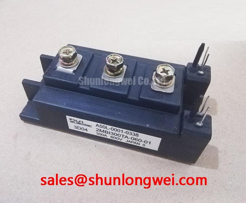
Transient Dynamics & Electrical Design: Galvanic Gate Drive Isolation and 2MBI300TA-060
The gate circuit should be treated as a complete high speed switching loop rather than as a simple control wire. Before connecting the module to a driver board, identify the gate and emitter terminals from the original Fuji Electric documentation. Do not infer terminal polarity from a visually similar module. With the device unpowered and isolated from the DC link, inspect continuity and resistance in the gate path, then compare the cold measurement with a known good reference where one is available.
Design Consideration: galvanic isolation between the control electronics and the power switching circuit is determined by the gate driver, isolation components, PCB construction, creepage, clearance, and enclosure environment. The supplied product data in this brief confirms the voltage, current, and module category, but it does not confirm a reinforced isolation rating above 5 kV or a CMTI value above 100 kV/µs for the complete gate drive system. Designers should verify those requirements from the driver and module documentation instead of assigning them to the IGBT module alone.
Keep the gate drive return path physically close to the corresponding emitter return path and minimize the area enclosed by the gate loop. This is an Engineering Recommendation intended to reduce parasitic inductance and ringing during turn on and turn off. The actual damping requirement depends on the driver output impedance, gate charge, switching speed, busbar geometry, and measurement method. A resistor or ferrite element may be evaluated as a Typical Starting Point during bench tuning, but its final value should be established from oscilloscope measurements of gate voltage and collector emitter transients.
When a drive produces intermittent overcurrent trips, inspect the gate waveform at the module terminals rather than at the driver output alone. An unexpected plateau, excessive ringing, or a difference between high side and low side switching may indicate a return path problem, isolation coupling, probe error, or driver timing issue. Verify the signal against the original schematic and examine the DC link waveform at the same time. The Fuji Electric 7th-Gen X-Series IGBT Modules information can provide useful manufacturer context for switching device families, but it should not be treated as a substitute for the exact data applicable to this model.
💡 Bench Tip: Use ESD controls and compare all cold state measurements with a documented known good reference before connecting the module to an energized inverter.
2MBI300TA-060 Thermal-Electrical Optimization: Thermal Interface Material Thickness and Practical Tuning
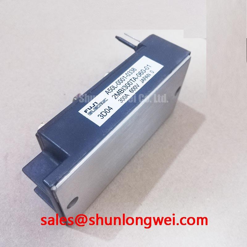
Mechanical installation directly affects electrical reliability because uneven mounting can increase thermal resistance and place stress on the module base. Clean the heatsink contact surface, remove particles, and inspect the base for visible distortion before applying thermal interface material. The exact recommended material and thickness must come from the relevant Fuji Electric mounting instructions; a generic thickness such as 50 to 100 µm is a Design Consideration only and must not be presented as an official value for this model.
Apply the interface material as a uniform, controlled layer. Excess compound can migrate toward terminals, while insufficient coverage can leave dry areas beneath the base. Tighten the mounting hardware progressively in a diagonal or manufacturer specified sequence so that contact pressure develops evenly. The correct screw type, torque, washer arrangement, and sequence remain system and documentation dependent. After mounting, inspect the busbar and terminal connections for flat seating, adequate creepage and clearance, and freedom from mechanical loading caused by misaligned conductors.
Incoming inspection should also verify the physical terminal arrangement against the original drive drawing. Use a low energy meter test only after confirming that capacitors are discharged and that parallel semiconductor paths will not distort the reading. A diode mode result is not a universal pass or fail signature for every IGBT module because the internal circuit arrangement, antiparallel diode path, external wiring, and meter current can affect the observed value. Record the test direction, instrument, ambient condition, and connection points so that later maintenance comparisons remain meaningful.
Vibration resistant fastening is a Design Consideration for industrial motor drives. Busbars should be supported independently where necessary so that their weight and movement are not transferred into the module terminals. After the first controlled energization, inspect for abnormal heating at the terminal joints and compare phase currents under the same operating condition. A thermal camera can help locate imbalance, but its emissivity setting and viewing angle should be controlled before interpreting small temperature differences.
For a broader view of coordinated power conversion stages, engineers may also review the 2MBI400TB-060-01 as a separate device reference for a possible front end or auxiliary stage. It is not an automatic substitute or guaranteed companion part. Voltage, current, topology, pulse duty, and mechanical compatibility must be checked independently.
2MBI300TA-060 Operational Boundaries: Evaluating Dynamic Braking Chopper Operation Limits
In a variable frequency AC motor drive, the braking chopper and ballast resistor must be evaluated as a coordinated energy path. During deceleration, the motor can return energy to the DC link. The chopper switching device, resistor, wiring, fuse protection, and DC link capacitor must all be assessed for the actual deceleration profile. The 600.0 V voltage rating and 300.0 A current rating are Official Specifications for product identification, not a complete braking duty guarantee.
System designers should determine the recovered energy, pulse duration, repetition rate, DC link operating voltage, resistor temperature, and semiconductor switching losses from the drive application. The resistor must absorb the expected energy without exceeding its own thermal limits, while the chopper must remain within the switching and junction temperature boundaries stated in the applicable documentation. Peak current, average current, and repetitive pulse current should not be treated as interchangeable quantities.
The term ITSM is commonly associated with thyristor surge current specifications. It should not be assigned to this IGBT module unless the exact Fuji Electric datasheet explicitly provides such a rating. Likewise, thyristor gate parameters such as IGT and VGT are not interchangeable with IGBT gate drive specifications. For this product, verify the required gate voltage, gate charge, switching conditions, and short circuit limitations from the exact technical document rather than importing figures from a thyristor or another IGBT family.
During commissioning, begin with controlled DC link conditions and monitor collector emitter voltage, gate emitter voltage, braking resistor current, and heatsink temperature. If the chopper trips during deceleration, possible areas for investigation include resistor sizing, braking command timing, DC link sensing, gate drive integrity, wiring inductance, and protection thresholds. The symptom alone does not identify one failed component. Compare the measured waveforms with the drive manufacturer's reference test conditions.
Fuji Electric provides a dedicated Brake Chopper IGBT Modules resource that is relevant when reviewing braking topologies. It does not establish interchangeability with the 2MBI300TA-060. Any replacement assessment should include electrical, thermal, mechanical, and control timing verification.
Field Diagnostics & Commissioning: Junction to Case Thermal Network Simulation in 2MBI300TA-060 Topologies
Thermal diagnostics should start with measured operating conditions rather than a predicted lifetime claim. Record output current, switching state, ambient temperature, heatsink temperature, airflow condition, and duration of the overload event. Then compare the measured case temperature with the value expected from the drive's documented loss model. The official information supplied for this product confirms the 300.0 A current rating, but it does not provide a transient thermal impedance curve or a guaranteed junction temperature margin.
A multi RC thermal model may be used as an Engineering Calculation when the correct junction to case data, power waveform, and boundary conditions are available. The model should represent the actual pulsed conduction and switching losses, not a simplified continuous current assumption. Engineers should calculate the transient junction response from the manufacturer's thermal network data, then validate the result with case temperature measurements and controlled load tests. If the necessary thermal coefficients are unavailable, report the result as an engineering estimate rather than an official device limit.
Check the module after a trip by isolating the DC link, waiting for the drive's discharge procedure to complete, and confirming the residual voltage with a properly rated meter. Inspect the gate terminals, power terminals, heatsink interface, and surrounding PCB for discoloration, loosened hardware, contamination, or tracking. Static resistance and diode mode checks can identify an obvious abnormal path, but they cannot verify dynamic switching performance, insulation capability, or thermal integrity.
For gate related faults, compare the gate waveform at the module pins with the emitter reference during both switching directions. Excessive oscillation may point to parasitic inductance, inadequate damping, driver saturation, probe grounding, or isolation coupling. The technical guide Evolution of Negative Off-Bias Gate Drive Circuits can be consulted as an engineering reference when evaluating off state gate control. Whether negative off bias is appropriate remains a system design decision and must be verified against the exact driver, isolation barrier, gate oxide limits, and switching conditions.
Replacement commissioning should preserve the original protection architecture wherever its ratings and timing have been verified. Confirm phase sequence, gate channel assignment, current sensor polarity, DC link precharge operation, braking command behavior, and fault interlock response before applying full motor load. Any change in busbar length, gate wiring, heatsink assembly, or driver board can alter the measured transient response, so the final acceptance test should use the actual repaired configuration.