
Content last revised on October 25, 2026
7MBR75U4R120-50 Thermal Electrical Optimization: Thermal Interface Material Thickness and Practical Tuning
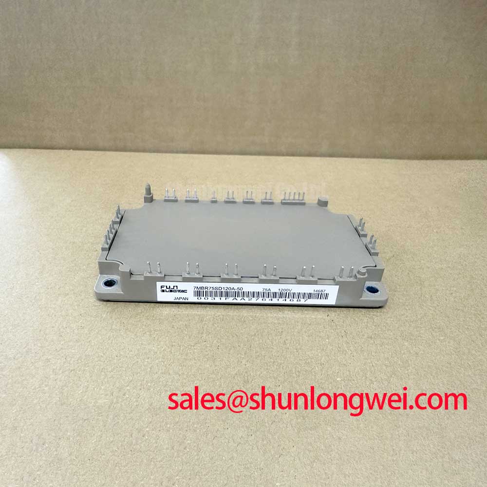
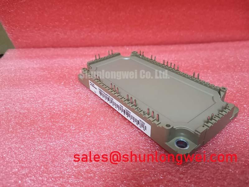
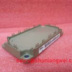
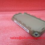
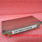
Start the incoming inspection with the thermal path: place the 7MBR75U4R120-50 on a verified flat heatsink surface, inspect the baseplate contact area, and confirm that the mounting footprint is free from burrs, old compound, oxide debris, and trapped particles. This Fuji Electric power module is specified at 1200.0 V and 75.0 A; those ratings identify the electrical class, while the actual thermal operating point remains dependent on switching conditions, cooling capacity, ambient temperature, and the complete drive design.
For a heavy duty variable frequency AC motor drive, the thermal interface material should form a continuous, controlled layer rather than a thick cushion. A practical Design Consideration is a thin TIM layer in the approximate 50 to 100 µm range when the selected compound and surface finish support that application. The target is not a visually heavy coating. The target is to fill microscopic surface irregularities while keeping the thermal path short. Excess compound can increase bond line thickness, migrate toward the terminals, and make the baseplate behave as though it is unevenly supported.
Apply the compound evenly across the intended contact zone and keep the material away from the electrical terminals and screw openings. A clean spreader or controlled dispensing method helps prevent ridges that can leave air pockets beneath the module. When a previously installed unit is removed, compare the imprint pattern on the heatsink and module base. A dry region, crescent shaped contact mark, or isolated thick area deserves attention because it can indicate surface curvature, uneven fastening, or a heatsink that is being pulled out of plane.
Baseplate curvature compensation should be handled mechanically rather than by adding more thermal compound. Check the heatsink with a suitable straightedge and inspect the module mounting surface under consistent lighting. If the assembly uses a compliant pad, spring washer, or clamping plate, confirm that its pressure is distributed across the mounting area. The compensation method is a system level engineering decision and should preserve the module manufacturer’s mounting instructions, electrical clearances, and allowable mechanical stress.
Use a sequential screw pattern that brings the module down progressively instead of fully tightening one corner first. Initial contact should be uniform, followed by staged tightening in a diagonal or manufacturer defined sequence. This reduces the chance of corner lift and helps the TIM settle consistently. The final fastening torque must come from the applicable Fuji Electric mechanical documentation or the approved equipment assembly specification, not from a generic value copied from another power module.
During service troubleshooting, a rising case temperature should be assessed alongside heatsink temperature, airflow, fan condition, compound condition, switching frequency, load profile, and the gate drive waveform. A warm module does not by itself identify a TIM fault. If the thermal imprint is uneven, remove the unit, clean both surfaces using an approved process, correct the mechanical flatness issue, and repeat the controlled installation. Designers evaluating the module for a variable frequency drive cabinet should also keep airflow paths clear of cable bundles and avoid placing heat sensitive control boards directly in the exhaust stream.
Bench Tip: Use ESD protection and record a cold mechanical and electrical baseline before applying thermal compound, because a later thermal change is easier to interpret when the original installation condition is documented.
Fuji Electric’s semiconductor information provides useful background on its power semiconductor and IPM product families through Fuji Electric Power Semiconductor and IPM Modules. When integrating this specific PIM into an existing drive, the engineer should match the module footprint, terminal arrangement, gate interface, cooling surface, and protection topology against the original assembly drawing.
Transient Dynamics and Electrical Design: Pollution Degree 3 Creepage Distances on 7MBR75U4R120-50
Audit the high voltage insulation path before applying switching power. For an approved insulation test between the electrical circuit and baseplate, remove external contamination and use an insulation tester with a controlled ramp and suitable discharge procedure. The responsible safety procedure and applicable manufacturer documentation must define the test voltage, duration, terminal grouping, connection points, discharge time, and pass or fail limits. Do not apply the insulation-test voltage across semiconductor junctions or between gate and emitter.
Pollution Degree 3 conditions require more than a nominal air gap. Industrial dust, moisture films, conductive residue, and repeated condensation can reduce the effective insulation margin along a surface. Inspect the complete terminal to baseplate route, including the module perimeter, nearby busbars, cable lugs, standoffs, and the enclosure wall. Creepage and clearance should be calculated from the working voltage, transient environment, insulation system, material characteristics, and applicable standard. The design engineer should verify the final dimensions against the equipment insulation coordination assessment rather than treating the module rating as a substitute for cabinet level spacing.
When an insulation test produces an unstable or unexpectedly low reading, first isolate the module from the external bus structure. Clean and dry the surrounding area, remove parallel paths through snubbers or measurement circuits, and repeat the approved test with the module disconnected from the gate driver and the terminals grouped as required by the test procedure. A change after isolation may point toward the external assembly, while a persistent reading requires closer examination of the module surface, substrate insulation path, and terminal contamination. Never infer a semiconductor junction defect from an insulation reading alone.
Switching control requires a low inductance gate loop, a suitable isolated driver, and a sourcing and sinking capability selected from the gate charge, switching frequency, desired transition behavior, and driver thermal limits. The gate resistor is a tuning component, not a universal fixed value. A larger external RG can slow the transition and reduce ringing, while a smaller value can increase switching speed and electromagnetic stress. The correct choice is determined by measured gate voltage, collector emitter overshoot, ringing, switching loss, and the safe operating limits of the complete converter.
Place the turn on and turn off gate resistance where the circuit topology requires it, and keep the driver return path separate from high current commutation paths. If the design uses a split resistor arrangement, verify that the diode orientation and pulse current path match the intended switching behavior. Gate emitter protection, Miller control, and negative bias are system decisions; they should not be added by assumption when the original drive schematic is unavailable.
A metal oxide varistor may be used in the wider overvoltage protection network, but it must be coordinated with the DC link, braking circuit, fuse strategy, surge energy, and enclosure clearances. The MOV is not a replacement for correct commutation layout. Minimize stray inductance in the power loop, place the snubber or clamp network according to the switching current path, and verify peak voltage during controlled switching tests. Common mode transient behavior also depends on the isolated gate driver or digital isolator, its CMTI performance, propagation delay, supply bypassing, and PCB return geometry. The module itself should not be described as independently providing EMC compliance for the finished drive.
For a repair engineer comparing physical fit and electrical topology, the 2MBI75UA-120 can be reviewed as a separate Fuji Electric module option. It should be treated as an objective comparison point only. Pin assignment, internal topology, mounting geometry, voltage class, current conditions, gate requirements, and thermal interface must all be checked before any substitution is considered.
7MBR75U4R120-50 Thermal Electrical Optimization: Torque Reaction Absorption and Practical Tuning
Check the main power connection assembly for mechanical reaction before reconnecting the DC link or motor phase conductors. The following screw-joint guidance applies wherever the surrounding assembly uses screw-fastened terminals or busbar joints; confirm the module’s own connection method from its mechanical drawing. At each screw-fastened joint, the terminal screw must engage correctly with the approved thread, the lug must sit flat, and the washer stack must apply pressure to the lug without pressing against an unintended plastic or insulating feature. A tilted lug can transfer tightening force into the terminal body and may place levering stress on connected conductors during vibration and thermal cycling.
Thread engagement should be confirmed with the approved screw length, washer arrangement, and terminal drawing. Excessive screw length can interfere with internal structure, while insufficient engagement can allow the connection to loosen under thermal movement. Do not use a longer fastener to compensate for a missing washer or a distorted lug. The mechanical specification for the terminal, including torque and any tightening sequence, must come from the relevant component documentation or the original equipment assembly instruction.
Flat washers and spring elements should be selected for the terminal design and environment. A spring washer or disc spring can help maintain contact force as the joint expands and contracts, but its working range, seating condition, and compression behavior must match the fastening system. For high current connections, contact pressure must remain stable without deforming the terminal surface. Inspect for radial marks, displaced plating, cracked lugs, or washer edges that have cut into the contact area.
During a field repair, support the cable or laminated busbar before loosening a terminal screw. Heavy conductors should not hang from the module connections, and the cable route should not impose side load after tightening. Provide sufficient bend radius and strain relief outside the module so that vibration is absorbed by the enclosure structure rather than transmitted directly into the power connections. This is particularly important in cabinets where fans, contactors, or motor cable movement create repeated mechanical excitation.
After installation, verify that the main conductors remain aligned when the cover is fitted and that no busbar or cable lug shifts as the fasteners are tightened. A useful inspection method is to mark the fastener head and adjacent stationary surface after the approved torque has been applied. The mark is not a torque substitute, but it can help reveal movement during later maintenance. Recheck the joint only under the equipment manufacturer’s service procedure and with the DC link fully isolated and discharged.
Cooling arrangements that use an intermediate heat spreader require careful attention to the mechanical stack. Both mating surfaces at each thermal interface must be clean, suitably flat, and free from burrs. The mounting structure should distribute pressure without bending the module baseplate or concentrating force at one edge. Any additional interface material must be compatible with the insulation requirements and the approved thermal design. Do not assume that the module housing provides a second cooling surface.
When a drive shows intermittent overcurrent, unexplained thermal drift, or noise that changes after cabinet movement, inspect the mechanical installation alongside the electrical waveform. Look for loose terminal hardware, copper discoloration, cable movement, distorted washer stacks, and evidence that the heatsink or busbar is loading the module. Then compare the phase connections, gate signals, and DC link measurements with a known good operating condition. The symptom may involve more than one mechanism, so the inspection should preserve the original wiring position and document each change.
For broader guidance on power module selection, switching behavior, thermal paths, and system reliability, consult the Power Electronics Masterclass. It can support the design review while the final installation remains governed by the 7MBR75U4R120-50 mechanical drawing, electrical ratings, gate drive design, and the equipment manufacturer’s validated assembly procedure.