


Content last revised on June 30, 2026
FP75R12KT4_B11: 1200V 75A PIM IGBT Module with TRENCHSTOP™ IGBT4
Product Overview & Key Specifications
An Integrated Solution for Efficient, Compact Motor Drives
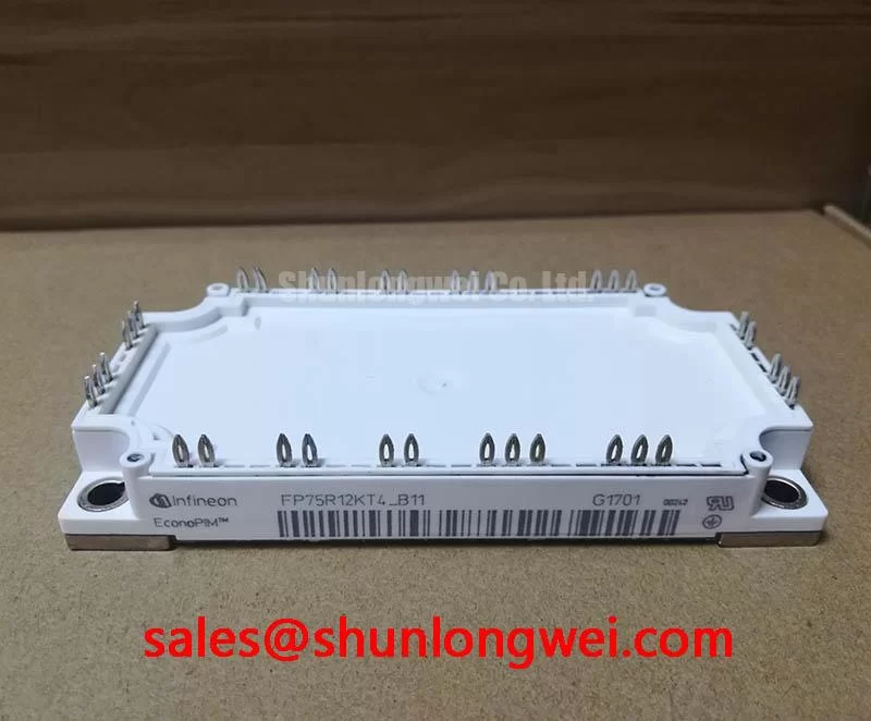
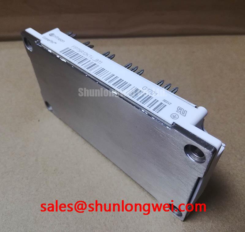
The FP75R12KT4_B11 is a highly integrated Power Integrated Module (PIM) designed to streamline the development of variable speed drives. It consolidates a three-phase input rectifier, a brake chopper, and a three-phase inverter into a single, thermally efficient EasyPIM™ 2B housing. Engineered with Infineon's TRENCHSTOP™ IGBT4 technology, this module delivers a well-balanced performance profile optimized for industrial motor control and servo applications. Its core specifications are: 1200V | 75A | VCE(sat), typ. 1.85V. Key engineering benefits include a significantly reduced system footprint and optimized switching characteristics for medium-frequency operation. For motion control systems requiring a compact and reliable power stage up to approximately 30 kW, the FP75R12KT4_B11 provides a robust, all-in-one solution.
Key Parameter Overview
Decoding the Specs for System-Level Performance
The technical specifications of the FP75R12KT4_B11 are structured to support detailed system design, from thermal management to electrical performance. The parameters below are detailed under typical operating conditions (Tvj = 25°C unless otherwise specified). For a comprehensive understanding of performance curves and application-specific data, consulting the official datasheet is critical.
| Inverter Stage - TRENCHSTOP™ IGBT4 | ||
|---|---|---|
| Parameter | Symbol | Value |
| Collector-emitter voltage | V_CES | 1200 V |
| Continuous DC collector current (Tc = 80°C) | I_C nom | 75 A |
| Repetitive peak collector current (tp = 1 ms) | I_CRM | 150 A |
| Collector-emitter saturation voltage (IC = 75A, Tvj = 25°C) | V_CE sat | 1.85 V (typ.) |
| Diode & Rectifier Stage | ||
| Repetitive peak reverse voltage (Rectifier) | V_RRM | 1600 V |
| DC forward current (Rectifier, per diode) | I_F(DC) | 50 A |
| Diode forward voltage (IF = 75A, Tvj = 25°C) | V_F | 1.95 V (typ.) |
| Thermal & Mechanical Specifications | ||
| Maximum junction temperature | T_vj max | 150°C (175°C overload) |
| Thermal resistance, junction to case (IGBT) | R_thJC | 0.19 K/W (per IGBT) |
| NTC thermistor resistance (R25) | R_25 | 5 kΩ ± 5% |
Download the FP75R12KT4_B11 datasheet for detailed specifications and performance curves.
Application Scenarios & Value
Achieving System-Level Benefits in Industrial Motion Control
The FP75R12KT4_B11 is an optimal power stage for systems where integration, reliability, and balanced efficiency are primary design drivers. Its PIM architecture makes it a natural fit for a range of industrial applications.
- Industrial Motor Drives: In applications like conveyor belts, pumps, and fans, the module's all-in-one design simplifies manufacturing and reduces the number of failure points. Its 75A rating provides ample capability for three-phase AC motors in the 15 to 30 kW power class.
- Servo Drives: A key challenge in Servo Drive design is achieving high power density in a constrained space. The FP75R12KT4_B11 directly addresses this by combining three power stages into one compact housing. The integrated NTC thermistor is crucial for enabling precise thermal monitoring, which is essential for protecting the drive during the rapid acceleration and deceleration cycles typical in CNC machinery and robotics.
- Air Conditioning Systems: The module's efficiency contributes to higher overall system performance in commercial HVAC applications, helping to meet increasingly stringent energy consumption standards.
For applications with lower current requirements, the related FP50R12KT4 offers a similar level of integration with a 50A rating, providing a scalable option within the same product family.
Technical Deep Dive
Implications of TRENCHSTOP™ IGBT4 for Drive Design
The selection of the TRENCHSTOP™ IGBT4 technology in the FP75R12KT4_B11 is a deliberate engineering choice that directly impacts its application suitability. Unlike newer IGBT generations that are heavily optimized for extremely low switching losses (E_on/E_off) at the expense of a higher forward voltage drop (VCE(sat)), IGBT4 strikes a different balance. It provides a moderate VCE(sat) of 1.85V (typ.), which is crucial for minimizing conduction losses—the dominant loss factor in motor drives operating at lower to medium switching frequencies (typically 4 kHz to 12 kHz).
Think of it like choosing tires for a vehicle. An ultra-high-performance racing slick (like a newer, faster-switching IGBT) is perfect for a smooth track but wears out quickly and is inefficient for daily driving. The IGBT4 is more like a high-quality all-season tire: it offers excellent, reliable performance across the most common operating conditions found in industrial drives. This balance makes the FP75R12KT4_B11 particularly effective in cost-sensitive applications where extreme switching speeds are not the primary requirement, but overall system efficiency and thermal stability are. This design choice simplifies the Thermal Management strategy, often allowing for a more compact and cost-effective heatsink design.
Frequently Asked Questions (FAQ)
How does the integrated NTC thermistor enhance the reliability of a Variable Frequency Drive (VFD)?
The integrated NTC thermistor provides a direct, real-time measurement of the module's baseplate temperature. This data allows the VFD's control system to implement precise over-temperature protection. By actively monitoring the thermal state, the controller can reduce output power or trigger a safe shutdown before the IGBT junction temperature exceeds its maximum limit, preventing catastrophic failure and extending the operational life of the drive.
What is the primary benefit of the PIM (Power Integrated Module) configuration for system design?
The primary benefit is system simplification. By integrating the input rectifier, brake chopper, and inverter into a single component, the PIM configuration drastically reduces the number of electrical connections, simplifies the PCB layout, shortens assembly time, and minimizes the overall physical footprint of the power electronics. This leads to lower manufacturing costs and improved system reliability due to fewer potential points of failure.
Engineering and Procurement Inquiries
To evaluate the FP75R12KT4_B11 for your specific application, or to request further technical documentation for your design team, please contact our sales department for assistance.