

Content last revised on September 26, 2026
FB30R06W1E3 Thermal and Electrical Behavior: Gate Turn-Off and Miller Clamp Evaluation
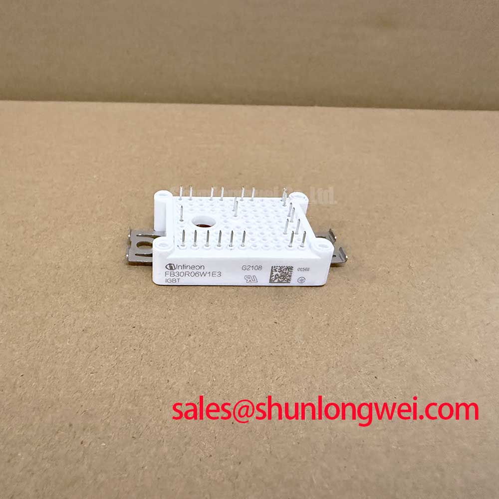
With the equipment isolated and the DC link discharged, compare the installed module’s terminal layout and cold-state terminal measurements with the equipment documentation before disturbing its gate wiring. The FB30R06W1E3 is an Infineon power integrated module in an EasyPIM™ 1B housing. Its stated electrical ratings establish an initial screening boundary, but they do not establish compatibility with a particular driver or power stage.
| Parameter | Value | Specification status |
|---|---|---|
| Collector-emitter voltage, VCES | 600 V | Official Specification |
| Rated collector current, IC | 30 A | Official Specification; applicable case-temperature and other rating conditions must be checked |
| IGBT saturation voltage, VCE(sat) | 1.45 V typical | Official Specification; measurement conditions must be checked |
| IGBT power dissipation, Ptot | 140 W | Official Specification; applicable thermal conditions must be checked |
| Gate threshold voltage, VGE(th) | 5.8 V typical | Official Specification; not a recommended drive voltage |
| Operating junction temperature, Tvj op | −40 °C to +150 °C | Official Specification |
| Housing | EasyPIM™ 1B | Official Specification |
Design Consideration: During turn-off, a rising collector voltage can couple through the gate-to-collector capacitance and lift the gate potential. If a driver provides an active Miller clamp, assess its connection and current path against the installed schematic; negative gate bias is another possible approach, not an assumed requirement for this module. Keep the gate return path compact to limit parasitic inductance and compare measured gate waveforms at the module terminals with the driver command. The system designer should determine bias, damping and dead time from switching tests under the actual DC-link and load conditions.
The typical 5.8 V threshold is a device characterization point, not evidence that the IGBT is fully on at that voltage. For the distinction between switching behavior and a particular module’s published ratings, Infineon’s reverse-conducting IGBT application note provides useful background. Its reverse-conducting device discussion must not be treated as a specification of the FB30R06W1E3.
FB30R06W1E3 Operational Boundaries: Overcurrent Detection and Turn-Off
Check the protection schematic before attributing a trip to the module. A fault present when a switch is commanded on and one arising while it is already conducting can produce different current and voltage trajectories. Design Consideration: Detection thresholds, blanking time and turn-off response should be validated against the applicable short-circuit operating limits in the complete manufacturer documentation and against the installed driver. The ratings listed above do not establish a permissible short-circuit duration, so a fixed response-time claim would be unsafe.
A staged or controlled turn-off strategy can reduce the abrupt current change that drives inductive voltage overshoot, provided it also clears the fault within the verified protection boundary. Capture collector-emitter voltage, gate voltage and current during controlled commissioning tests; check peak voltage against the 600 V rating rather than inferring protection from a trip indicator alone. RC snubbers and a coordinated MOV network are circuit-level options for transient management. Their placement and ratings depend on measured energy and wiring inductance, not on the module nameplate by itself.
For a repair assessment involving electric material-handling or forklift traction equipment, verify the original inverter topology and DC-link conditions before treating the FB30R06W1E3 as a candidate. Phase-angle control and line-frequency ripple belong to an upstream controlled-rectifier assessment only where that circuitry actually exists. Similarly, FS100R12N2T4 can be examined as a separate power-stage device in a broader system review; its topology and ratings should not be assumed to make it a matching rectifier for this module.
When evaluating another catalog item such as BSM100GAL100D, compare circuit function, terminal assignment, housing, gate-drive requirements and thermal interface before considering any substitution. A shared IGBT label does not establish a direct replacement.
FB30R06W1E3 Operational Boundaries: Dynamic Loss and Pulsed Thermal Loading
Separate steady conduction from switching events when reviewing a recurring overtemperature trip. The stated 1.45 V typical VCE(sat) is relevant to conduction loss only at its specified test conditions; it is not a fixed voltage across every operating current and junction temperature. Switching loss also depends on the installed gate drive, bus voltage, current and switching frequency. Inspect captured waveforms and the equipment’s operating profile rather than applying a generic loss figure to the module.
Engineering Calculation: Where validated junction-to-case transient thermal-impedance data and a defensible loss profile are available, estimate junction temperature by applying the time-varying dissipation to that thermal response and adding the measured case-temperature baseline. A multi-RC representation can support this calculation, but its coefficients cannot be inferred from the 140 W dissipation rating. Check the resulting peak and repeated-cycle temperatures against the published −40 °C to +150 °C operating junction range, including uncertainty in the measurements and cooling conditions.
For equipment with bidirectional battery charging and discharging, compare heating during each power-flow mode and during transitions. Repeated thermal cycling is a reason to inspect cooling and contact condition, not a basis for stating a service-life figure without supporting test data. If a trip follows a load pulse, inspect the heatsink airflow, case-temperature trend and gate waveforms together; an apparent thermal symptom need not have a single cause. The Ultimate IGBT Knowledge Base provides additional switching and thermal concepts for that fault review. An IGBT7 module technology article discusses a different generation and must not be used to assign its construction or performance to this E3 part.
Assembly Integrity and Thermal Interface for FB30R06W1E3
Before mounting, inspect the heatsink contact area and module mating surface for contamination or damage, then confirm the installed footprint and terminal clearances against the equipment drawing. Design Consideration: Apply thermal interface material uniformly and avoid trapped air; the appropriate material, thickness and mounting sequence must follow the module documentation and the qualified assembly process. Do not compensate for a visibly uneven contact surface by adding an unverified layer of compound.
Use the specified fasteners and follow the applicable mounting sequence and torque instructions for the actual assembly. A uniform contact pattern matters because localized gaps can raise junction temperature even when airflow appears adequate. After installation, verify terminal connections, gate wiring separation and heatsink attachment before energizing the DC link.
⚠️ Maintenance Note: With power isolated and the DC link discharged, check heatsink cleanliness, contact-temperature trends and the cooling airflow during scheduled inspections. If moisture or condensation is present, assess the enclosure and operating environment before returning the equipment to service; the stated junction-temperature range does not by itself qualify the complete assembly for condensing conditions.