



Content last revised on September 13, 2026
Sharp LQ10D131 Industrial LCD Panel for Field Replacement
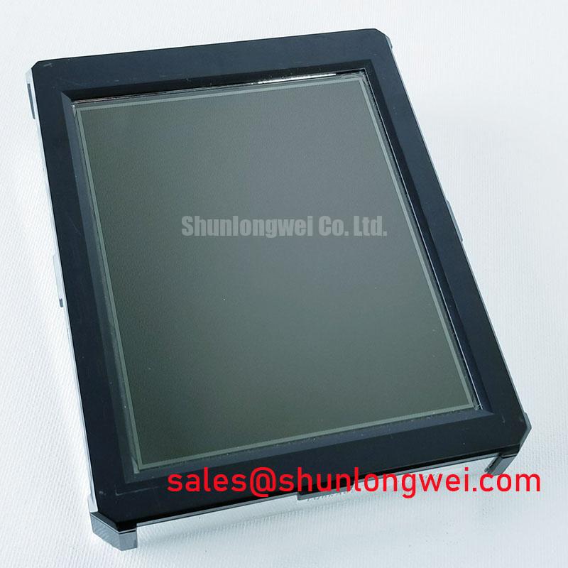
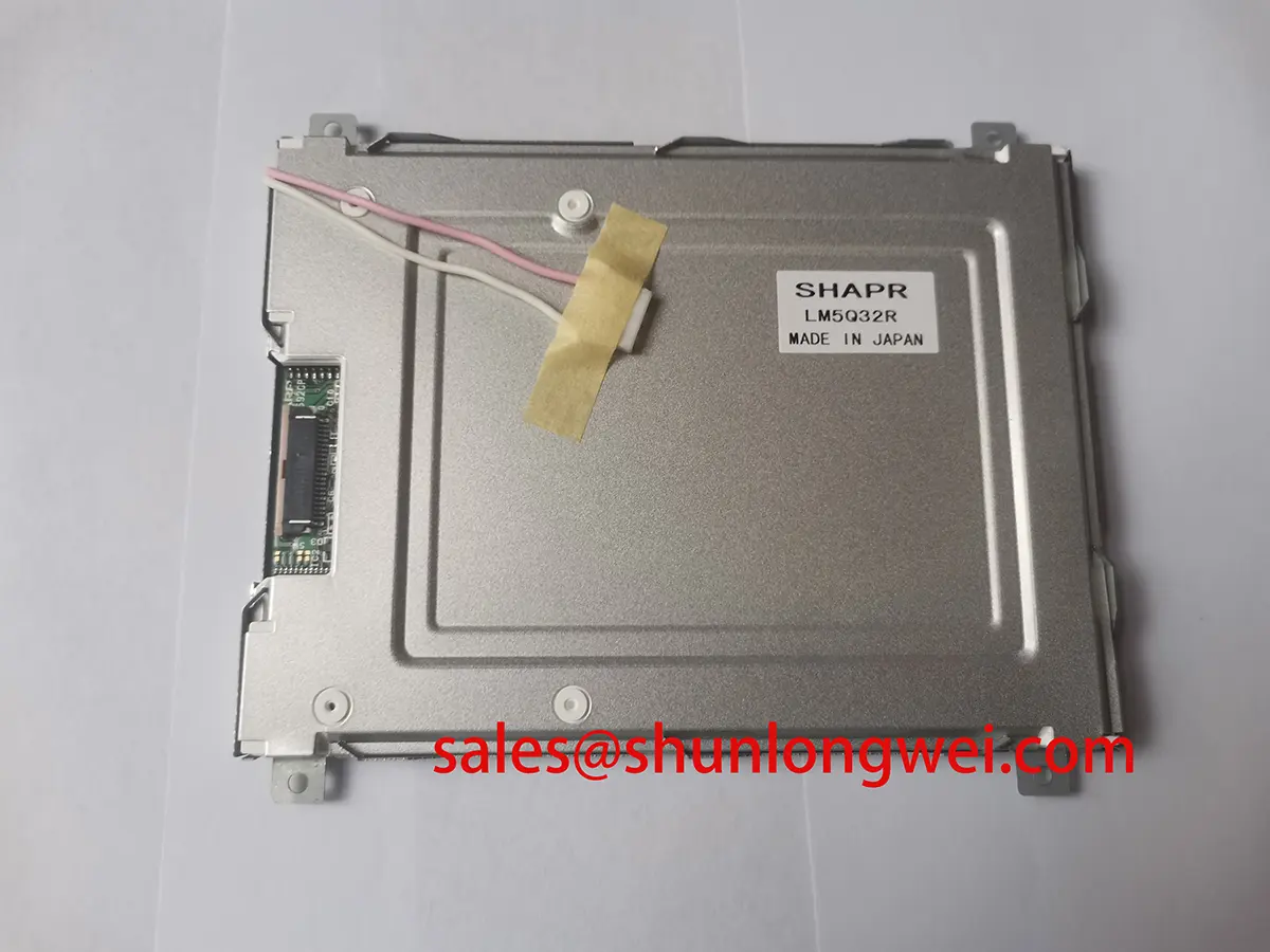
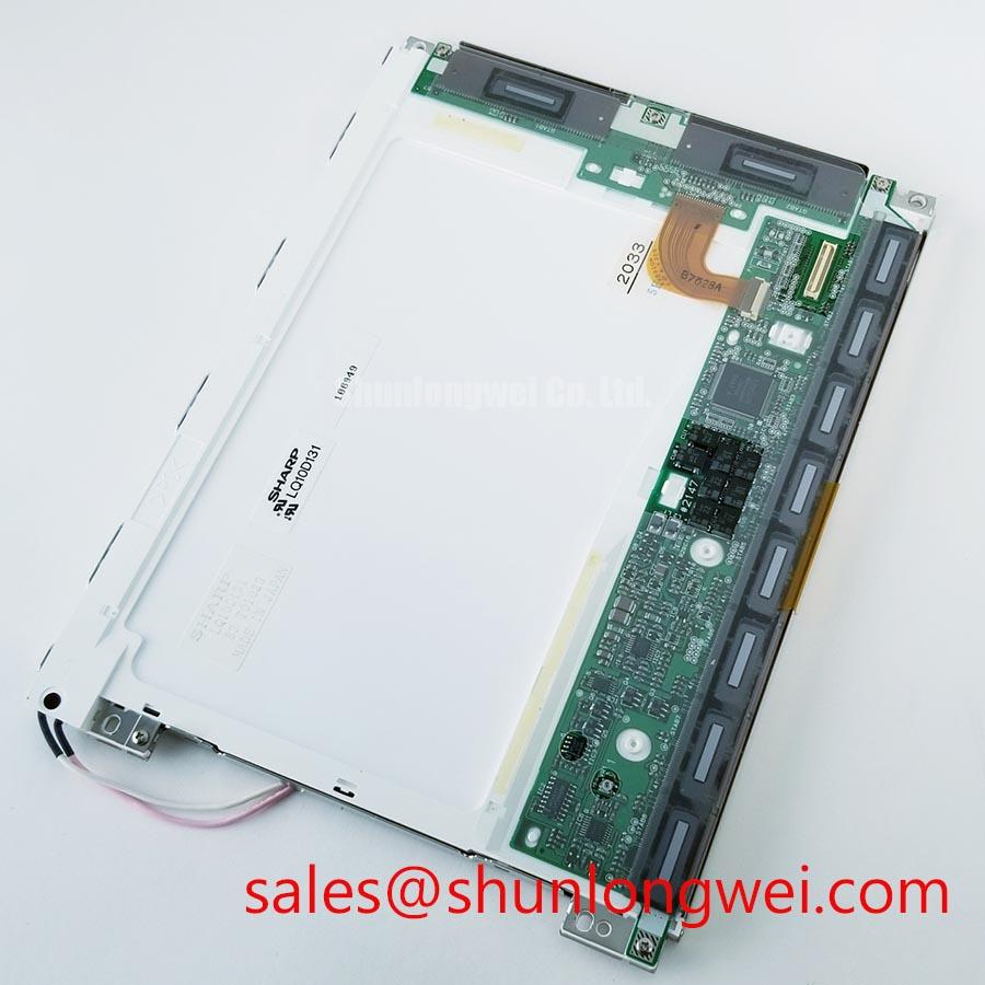
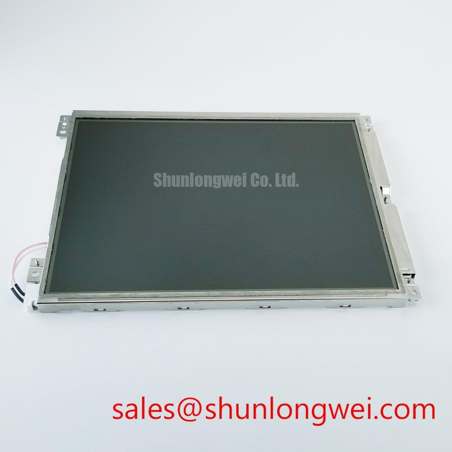
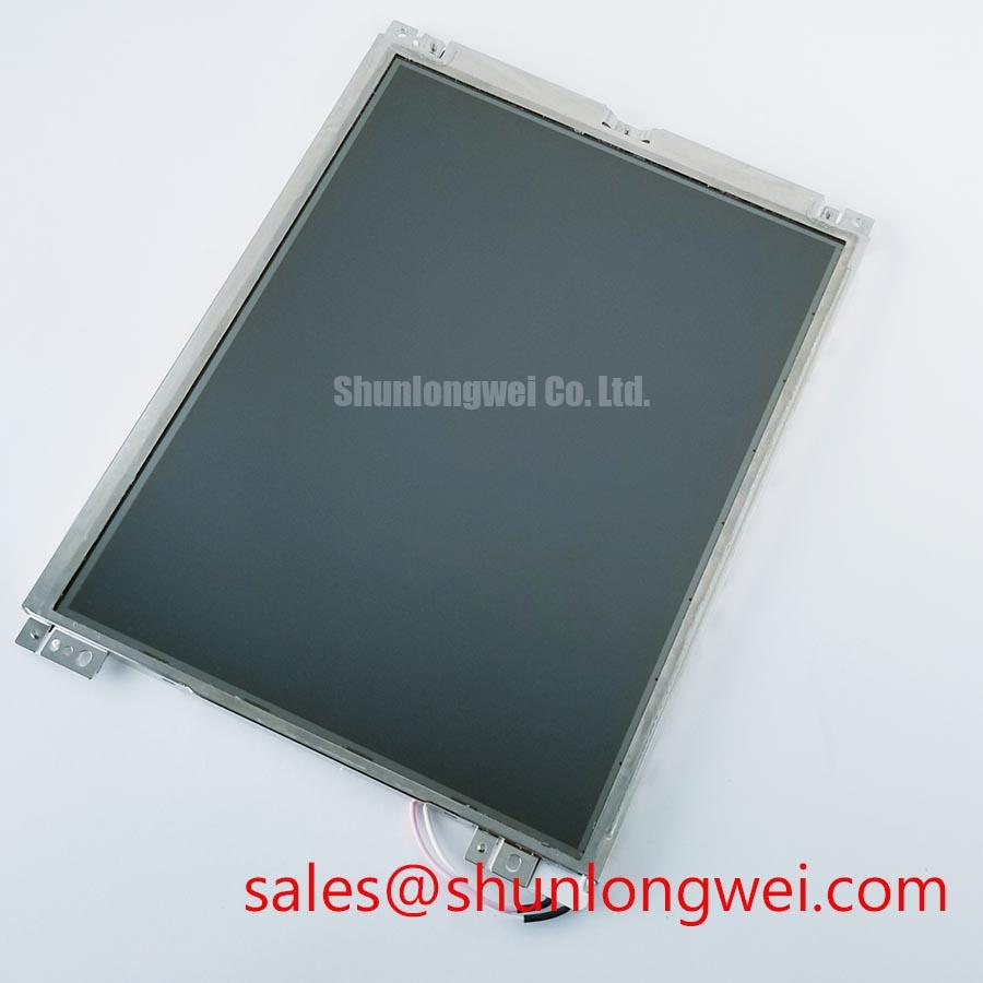
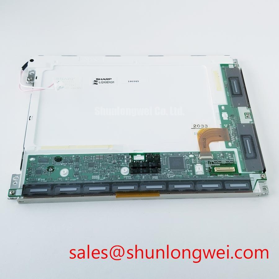
Begin the bench check by matching the removed panel’s label with LQ10D131, then inspect the bezel, connector area, mounting points, and visible display surface before applying power. This part is identified in the supplied factory context as a Sharp industrial grade LCD/HMI panel in a TFT LCD display module package. The available product record marks its factory specification status as Official Factory Spec Verified.
For a repair engineer, that identification step matters because a visually similar LCD module can differ in interface assignment, backlight control, mechanical envelope, optical direction, and power sequencing. The information supplied for this product confirms the manufacturer, category, module form, and model number, but it does not confirm numerical values for resolution, active area, supply voltage, luminance, viewing angle, response time, backlight current, connector pinout, or operating temperature. Those values should be checked against the original Sharp documentation and the equipment service record before installation.
Thermal Expansion Clearance Sizing across Heavy Industrial Metal Enclosure Cutouts
When replacing the display in a metal operator station, first compare the original cutout drawing with the physical envelope of the LQ10D131. Check the bezel seating surface, screw locations, cable exit direction, and the clearance between the display face and the enclosure. A rigid enclosure can transfer local mechanical stress into the panel when the chassis expands, contracts, or becomes distorted during door closure. The correct engineering objective is even support without twisting the display module.
The supplied engineering brief references cross pattern fastening and an M3 torque range of 0.35 to 0.45 N·m. Treat this as an Engineering Recommendation for the described installation method, not as an official Sharp factory specification for the panel. The final torque must be confirmed against the enclosure manufacturer’s fastener material, thread condition, washer arrangement, and service procedure. Tighten progressively across the mounting pattern while checking that the bezel remains level and that no corner is forced against the cutout.
Localized pressure can present as uneven brightness, dark areas, or optical nonuniformity after the assembly is closed. These symptoms do not establish a single cause. Reopen the enclosure, inspect the seating surfaces, and compare the panel while it is free from frame pressure. Also check whether a cable bend, gasket, label, or nearby bracket is pressing against the module. Do not add spacers or compressive pads unless their effect on the original mechanical design has been evaluated.
Backlight control requires the same separation between confirmed specification and system design. The supplied design target references PWM operation in the 200 Hz to 1 kHz range. This is a Design Consideration for evaluating visible flicker, camera banding, audible interaction, and dimming smoothness. It is not confirmed here as an LQ10D131 factory rating. The integrator should verify whether the replacement panel accepts PWM directly, requires a dedicated backlight driver, or depends on the host display controller.
When assessing duty cycle behavior, observe the panel at minimum, midrange, and maximum brightness while monitoring the backlight control waveform and supply stability. A setting that appears acceptable to the eye can still create image capture problems for maintenance cameras or inspection systems. Dimming linearity is determined by the complete panel and driver combination, so system validation should use the actual controller and cable assembly.
Normally White TN Grayscale Inversion Mitigation and Optimal Viewing Direction Alignment
Do not assume the viewing characteristics of the replacement from the screen size or TFT LCD label alone. The supplied factory information does not state whether the LQ10D131 uses TN, IPS, MVA, or another liquid crystal mode, and it does not provide a numerical viewing cone. The original panel documentation remains the authority for viewing direction, contrast behavior, grayscale response, and optical surface treatment.
If the service document identifies a normally white TN configuration, evaluate the screen from the same operator position used by the original equipment. TN panels can show grayscale changes when viewed away from the intended vertical or horizontal direction. This can affect alarm colors, trend traces, numerical readouts, and low contrast status indicators. The practical mitigation is to align the display plane and operator sightline with the original design rather than attempting to correct the issue through software contrast settings.
Any claim involving an 85 degree viewing value in four directions should be treated as a separate panel specification unless it is explicitly listed for LQ10D131. Such a figure cannot be transferred from an IPS or MVA panel to this Sharp model without documentation. The same caution applies to anti glare treatment. Under strong ambient lighting, inspect reflections from the actual enclosure window, protective cover, and display surface together. A surface that looks suitable on an open bench can become difficult to read behind a transparent door or under overhead plant lighting.
Grayscale inversion checks should use the equipment’s real test screens. Display a dark background with midlevel gray bars, fine text, and alarm graphics while changing the viewing angle gradually. Record whether the information remains readable at the operator’s normal standing and seated positions. If the screen is installed in a tilted door, validate the upper and lower viewing limits separately. This is an Engineering Recommendation, not a substitute for the manufacturer’s optical data.
Backlight troubleshooting should begin at the driver and connector rather than at the liquid crystal layer. A dark screen with a visible image under controlled illumination can indicate a backlight or driver path issue, but it does not identify the failed component by itself. Verify the host supply, enable signal, dimming signal, connector seating, and cable continuity against a known good assembly. If the driver reports an open load or short load condition, capture that diagnostic output before cycling power. The protection response belongs to the driver design unless the LQ10D131 documentation explicitly assigns the function to the panel.
For a same size or same resolution replacement assessment, engineers may also review LM190E08 TLG6. It should be treated as a separate compatibility candidate, not an automatic substitute. Mechanical dimensions, connector mapping, timing, optical direction, backlight control, and enclosure certification requirements must be compared before any purchasing or installation decision.
Suppressing Localized Thermal Gradients to Prevent Chronic Optical Yellowing and Color Shift
Temperature checks should be taken at the display perimeter, backlight driver area, cable entry, and nearby enclosure surfaces during a representative operating cycle. The supplied product information does not provide a thermal resistance value, LED lifetime curve, L70 rating, B50 rating, heater requirement, or guaranteed cold start time for LQ10D131. Do not convert generic LCD or LED industry figures into model specific lifetime claims.
A heat spreader rail or conductive frame can be considered when the enclosure creates a persistent local hot spot. This is a Design Consideration. The rail must not press against the active display area, obstruct the backlight path, interfere with insulation, or create a new thermal path into a sensitive connector. The system designer should measure the temperature distribution with the final cover, gasket, controller, and cable routing in place. The objective is a stable and even thermal environment, not a prescribed rail size or material that has not been specified by Sharp.
Reports of gradual yellowing, uneven white balance, or reduced brightness require comparison with a reference display and a review of operating conditions. Possible contributors can include cumulative heat, driver current regulation, optical aging, contamination, enclosure exposure, or changes in the viewing environment. A single visual symptom is not proof of LED aging. Record the controller settings, backlight command, supply condition, and temperature, then compare them with the original service baseline.
The requested reference to 50,000 hours and a 50 percent brightness point must not be presented as an LQ10D131 rating because that value is not included in the supplied factory parameter set. LED lifetime is dependent on junction temperature, drive current, thermal path, switching conditions, and the manufacturer’s test definition. If the original Sharp datasheet provides L70, B50, MTBF, or another lifetime metric, use that exact definition and test condition. Without such a source, the responsible field approach is condition monitoring rather than a promised operating-hour figure.
Cold operation needs a similar verification process. Liquid crystal response can become slower at low temperature, while the backlight driver and host controller may have different start behavior. The supplied brief refers to subzero evaluation between −20°C and −30°C, but these values are not confirmed as the official operating range of LQ10D131. They should therefore be used only as a proposed test condition when the equipment environment requires it, subject to the original panel documentation.
For a cold start test, allow the complete display assembly and controller to reach the target ambient condition before powering the unit. Observe the first image, gray transitions, alarm text, backlight stability, and recovery time after a brightness change. If a heater strip is being considered, its control method and thermal limit must be determined by the system designer. The heater should not be enabled solely because the display appears slow; first separate liquid crystal response, host timing, backlight startup, and cable or connector behavior.
⚠️ Field Alert: Disconnect power before inserting or removing the display cable, because live connector handling can expose signal and backlight circuits to unwanted electrical stress.
Radiated Emissions Evaluation and Backplate Grounding around Variable Frequency Drives
Install the replacement using the original cable route whenever possible, then inspect the shield termination, connector retention, backplate contact, and separation from high energy switching conductors. Pixel jitter, horizontal noise bands, intermittent image loss, or unstable backlight behavior near a variable frequency drive can involve cable coupling, grounding impedance, supply disturbance, connector contact, or controller timing. The observed symptom does not establish a single fault path.
Multi point contact between a conductive backplate and the enclosure can be considered where the equipment grounding architecture supports it. This is a Design Consideration, not a stated LQ10D131 certification or guaranteed EMC solution. The integrator should define the intended current return path, avoid accidental loops, and verify the result with the complete operator station assembled. A component or display module cannot independently claim compliance with whole equipment standards such as CISPR Class A or Class B.
For shielded FFC or LVDS wiring, preserve the original shield termination method and keep the high speed path away from motor drive output cables. Common mode ferrites may be evaluated when conducted or radiated interference remains after cable routing, connector seating, and power integrity have been checked. Ferrite selection is system dependent; its impedance profile, saturation behavior, mechanical location, and effect on signal quality require measurement on the actual interface.
Use an oscilloscope at the source and receiver sides of the display link when the image is unstable. Compare clock and data activity with a known good panel or a confirmed working machine. Check whether the disturbance follows the motor drive switching event, the backlight command, door movement, or cable position. This approach distinguishes signal integrity problems from display optical faults without assigning an unsupported voltage threshold or failure percentage.
The same discipline applies to a hazardous petrochemical Zone 2 explosion proof operator station. The LQ10D131 is identified here as a Sharp TFT LCD display module, not as an independently certified explosion proof assembly. The complete station must be assessed for enclosure construction, cable entries, thermal behavior, grounding, protective equipment, and applicable site certification. Designers should verify that the panel’s mechanical and electrical documentation matches the certified system design before field deployment.
For broader enclosure, grounding, thermal, and HMI integration considerations, review the Industrial Display and HMI Solutions engineering guide. It can support system level evaluation, while the original Sharp documentation remains necessary for any unlisted LQ10D131 electrical, optical, environmental, or lifetime parameter.
| Item | Confirmed product context | Integration status |
|---|---|---|
| Model | LQ10D131 | Official product identification |
| Manufacturer | Sharp | Official product identification |
| Category | Industrial grade LCD/HMI panel | Official product context |
| Package | TFT LCD display module | Official product context |
| Specification status | Official Factory Spec Verified | Use original documentation for unlisted values |