Content last revised on November 6, 2026
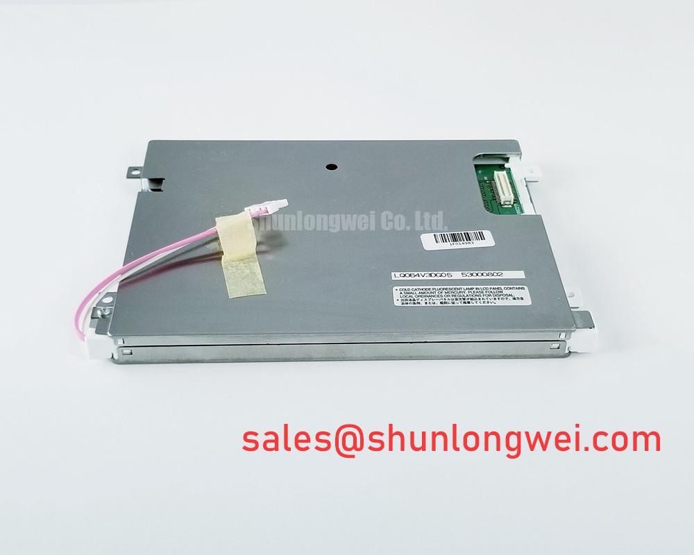
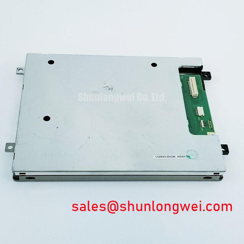
LQ065Y5DG02 Display Module: Identification and Integration Checks
- Confirm the module’s exact connector, pin assignment, and host interface from the panel documentation before connecting it.
- Compare the display outline, mounting points, and active viewing area with the equipment’s mechanical drawing.
- Check the specified supply rails and power-on sequence against the host board; do not infer them from the model number.
- Review the backlight drive requirements and the host driver’s fault indications before testing.
LQ065Y5DG02 is identified as a Sharp TFT-LCD active-matrix color display module. The available product information identifies the product category and construction, but does not establish electrical ratings, resolution, viewing angles, optical coatings, connector pinout, or backlight characteristics. Those details matter when evaluating a replacement: a matching model designation alone does not establish electrical or mechanical compatibility.
| Model | LQ065Y5DG02 |
| Manufacturer | Sharp |
| Product category | LCD display module |
| Display construction | TFT-LCD active-matrix color display module |
| Electrical and optical ratings | Use the original panel documentation for confirmed values |
Surface Readability: Assessing Anti-Glare and Anti-Reflective Treatments
Assess the actual cover surface and image quality under the lighting conditions where the equipment will operate; an anti-glare or anti-reflective treatment is not established by the baseline product information. Anti-glare textures can diffuse reflections, while anti-reflective treatments can reduce surface reflections through a different optical approach. Either choice involves trade-offs: surface haze, contrast perception, cleaning method, and viewing angle can affect legibility. Do not treat a coating as present unless the exact panel documentation or physical specification confirms it.
Viewing-angle behavior also depends on the panel technology. If the installed panel is TN, grayscale appearance can change with viewing position; IPS and MVA designs have different viewing characteristics, but neither should be attributed to this model without confirmation. For a repair, compare the displayed grayscale and color at the normal operator position and at the angles imposed by the bezel. Check whether the bezel or protective window adds reflections or clips the visible area. A high-ambient-light evaluation should use the actual enclosure and representative illumination rather than an assumed contrast figure.
At low temperatures, liquid-crystal response may slow, so transitions can appear smeared or lagged during cold starts. This is a general display consideration, not a confirmed operating limit for the LQ065Y5DG02. If a system uses a heater, evaluate its control behavior and temperature uniformity as part of the complete assembly, rather than assuming the panel includes one. Sharp Devices Europe Industrial Display Solutions and the Sharp Display Solutions Official Portal provide manufacturer display context; confirm model-specific details in the applicable documentation.
Operating Temperature and Sub-Zero Liquid-Crystal Response
Cold-start evaluation should focus on the panel’s documented operating range and the actual image response after the assembly reaches its intended environment. Liquid-crystal viscosity generally increases as temperature falls, which can lengthen pixel transitions and alter motion appearance. A slow transition, temporary image persistence, or uneven response should be recorded alongside ambient and panel temperatures, warm-up conditions, and the displayed pattern. These observations help separate temperature-related behavior from signal timing or host-processing faults without assigning an unsupported cause.
Thermal cycling also places demands on the complete display assembly, including its frame, adhesive joints, cable routing, and perimeter sealing. Inspect the assembled unit for mechanical stress and for changes in the visible image after temperature exposure. Do not infer a temperature rating or sealant type from the product category. Where sunlight readability is important, assess the panel with the intended cover glass and enclosure, since reflections and transmission losses can change the result materially.
When considering the LQ065Y5DG02 for a railway passenger information system or cab signalling display, treat the application as a compatibility evaluation, not a stated product qualification. The equipment designer should check documented temperature limits, image legibility, mechanical fit, and the environmental requirements of the complete terminal. For broader installation and test considerations, consult Industrial Display & HMI Solutions.
Eye-Diagram Voltage Margin and Differential-Noise Verification
In a high-vibration equipment bay, inspect the signal path for intermittent contact, cable strain, and coupling from nearby switching circuits before attributing image noise to the panel. Horizontal bands, flicker, or unstable pixels can arise at multiple points in the display chain. Compare the affected unit with a known-good signal path and use suitable probing at the host interface to determine whether the source signal remains stable under operating conditions. The interface type for this model is not established here, so do not assume LVDS or prescribe a particular termination arrangement.
💡 Pro Tip: Route display signals away from high-noise switching paths where practical, secure the cable against vibration, and verify image stability on the assembled equipment.
Shielding and grounding should be treated as system-level choices. A shield connected incorrectly at the equipment boundary can introduce unwanted current paths, while a poorly restrained cable can intermittently disturb the connection. Review the host and panel grounding scheme together, then compare behavior with motors or other switching loads inactive and active. If noise appears only during switching, examine the signal and power paths for coupled interference before changing panel settings. Any ferrite or filtering component should be selected and validated for the actual system rather than assumed to be part of this module.
LVDS Timing, Pixel Clock and Skew: Verify the Actual Panel Interface
Start interface validation with the original panel pinout and the host board’s documented output format. Do not infer a 20-pin or 30-pin connector, LVDS signaling, logic voltage, pixel clock, or JEIDA/VESA mapping from the model number. A mismatch in data mapping or signal timing can produce color errors, split images, unstable synchronization, or a blank screen, but those symptoms require checks across the host, cable, and display before diagnosis.
For an LVDS implementation, the design team should compare the transmitter and receiver requirements, differential-pair routing, clock-to-data relationship, and any stated timing margins. Use the interface documentation to establish the required supply and power sequence; an assumed voltage or rise-time window is not a substitute for the panel specification. When commissioning, capture the signal at the appropriate test point and compare it with the expected host timing, while checking cable seating and connector orientation. Avoid hot-plugging unless the equipment documentation explicitly permits it.
Backlight behavior also belongs to the system integration check. Confirm the specified drive method, dimming control, and fault response from the panel and host documentation. If the system uses an LED constant-current driver, distinguish an open-load or short-circuit indication from a panel-image fault, and follow the driver’s own protection and diagnostic guidance. Do not assume that the display module provides open/short protection, a particular overvoltage threshold, a PWM frequency, or a stated service-life figure. During replacement selection, compare documented dimensions, active area, connector, interface, and optical requirements before treating another listing, such as TCG070WVLPCANN-AN00, as a candidate; its suitability cannot be inferred from a product link alone.