

Content last revised on September 10, 2026
NL10276AC30-02 NEC Industrial Grade LCD HMI Panel
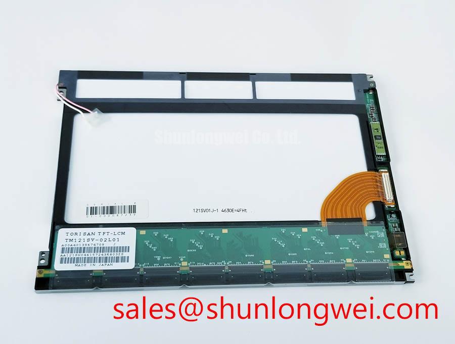
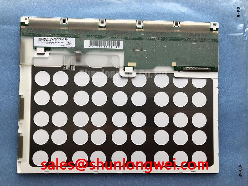
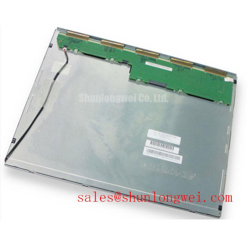
Disconnect the equipment, inspect the display module and connector area, and verify the replacement marking against the original service documentation before applying power. The NEC NL10276AC30-02 is identified in the available factory specification context as an Industrial Grade LCD/HMI Panel in a TFT-LCD Display Module format. This page separates confirmed product information from system-level integration considerations so maintenance engineers can evaluate the panel without assuming unverified interface or electrical values.
| Item | Verified information |
|---|---|
| Model | NL10276AC30-02 |
| Manufacturer | NEC |
| Product category | Industrial Grade LCD/HMI Panel |
| Construction designation | TFT-LCD Display Module |
| Identification status | Model and product category identified in the available factory context |
| Typical evaluation context | Industrial automation CNC operator panels and robot teach pendants, subject to system compatibility checks |
The available product data does not confirm the panel’s diagonal size, native resolution, viewing direction, luminance, contrast ratio, backlight technology, supply voltage, signal format, connector pinout, or mechanical cutout dimensions. Those values should be taken from the original NEC documentation or the equipment manufacturer’s service records before installation. The system integrator should verify the required supply voltage from the original panel documentation rather than assuming a value from a visually similar display.
Flush-Mount Open-Frame Bezel Integration and Perimeter Gasket Shock Isolation
For a CNC operator panel or robot teach pendant, begin with the mechanical envelope rather than forcing the display into the existing opening. Measure the original panel cavity, bezel opening, mounting-hole pattern, connector clearance, and cable exit direction. The NL10276AC30-02 is identified as a TFT-LCD Display Module, but the available factory context does not provide a confirmed outer bezel drawing or mounting-hole dimension. A replacement assessment therefore requires comparison with the original mechanical drawing or a controlled measurement of the removed unit.
An open-frame display can be damaged by uneven clamping even when the image initially appears normal. The mounting frame should support the perimeter without pressing on the active viewing area. A compliant gasket may be evaluated as a Design Consideration where the enclosure is exposed to vibration, repeated door movement, or impact from operator handling. Its purpose is to distribute contact pressure and reduce direct mechanical transfer into the glass assembly; the gasket material, thickness, compression, and environmental rating remain system-design decisions.
Use a cross-pattern tightening sequence when the panel is secured. This helps prevent one corner from being pulled down before the opposite side is supported. The suggested 0.35 to 0.45 N·m fastener range is an Engineering Recommendation for the stated integration approach, not an official NEC specification for this model. The equipment builder should confirm the fastener size, thread engagement, washer arrangement, frame stiffness, and final torque against its own mechanical design. A torque value must not be treated as permission to compress the display glass or bezel beyond the approved drawing.
After mechanical installation, inspect the screen with a uniform white image and then with dark grey or black content. Look for localized brightening, dark-field patches, pressure marks, or changes that appear when the frame is lightly supported. These observations do not establish a single failure cause, but they can indicate that the mounting interface needs to be reviewed. Remove mechanical pressure and repeat the test before investigating the controller or image source.
The proposed direct-sunlight performance target of greater than 500:1 at 50,000 lux is not confirmed as an official specification for the NL10276AC30-02. It should be treated only as an application evaluation criterion when the display is used near an open factory door, a machine window, or a brightly lit inspection station. Contrast perception depends on luminance, reflections, viewing angle, surface treatment, enclosure geometry, and the displayed content. The available information does not confirm an anti-glare coating for this model, so the integrator should verify the panel documentation and assess the assembled enclosure under actual lighting.
⚠️ Field Alert: Disconnect power before removing or inserting the display cable because an energized connector can expose signal and supply contacts to unintended electrical stress.
Optical Luminance Evaluation and Backlight Modernization Boundaries
When a field panel becomes dim, first separate the image-generation path from the illumination path. Apply a known-good test pattern if the control system permits it, then use an angled flashlight inspection to determine whether image information is still present beneath the dark screen. A faint image can suggest that the display timing and pixel drive path require separate testing from the backlight circuit, but it does not by itself identify the failed part.
The available factory information identifies the unit as a TFT-LCD Display Module but does not confirm whether this specific suffix uses CCFL or LED backlighting. It also does not confirm a cold-ignition voltage, LED current, PWM dimming range, brightness rating, half-life, or backlight MTBF. The stated CCFL ignition range of 1500 to 1650 Vrms, a 1000:1 PWM dimming ratio, and a 50,000-hour brightness-life claim must not be assigned to this model without a supporting NEC datasheet or a documented assembly specification.
For that reason, an LED modernization project should be treated as a system retrofit rather than a direct assumption about the original panel. The engineer should identify the original lamp or LED arrangement, inverter or driver interface, enable signal behavior, dimming method, connector pinout, thermal path, and available enclosure space. A constant-current driver may be considered where the replacement light source requires it, but its voltage range, current regulation, startup behavior, fault response, and dimming control must be matched to the retrofit assembly.
Do not connect a replacement backlight driver to the existing panel until the power and control pins have been traced against the original documentation. Acoustic noise, uneven illumination, startup hesitation, or flicker can result from a mismatch among driver switching behavior, lamp or LED load characteristics, mechanical coupling, and control timing. The correct diagnostic sequence is to monitor the supply and enable signals, compare them with a known-good unit where available, and then test the backlight separately from the video path.
The related NL10276BC30-24D may be reviewed as a separate NEC display reference when engineers are mapping a broader display solution or examining a related backlight and interface topology. It should not be treated as an automatic replacement for the NL10276AC30-02. Physical dimensions, optical characteristics, connector allocation, timing requirements, and mounting details must be verified independently for every candidate panel.
High-speed display wiring also requires documented interface identification. The available specification context does not confirm LVDS, eDP, RGB, or another signal architecture for this model. Consequently, a differential impedance target of 100 Ω ± 10% and a skew budget of 50 ps or less are not official NL10276AC30-02 specifications. They may be used only as Design Considerations if the system documentation confirms a differential display link. The final cable, termination, routing, and signal-integrity limits must be determined from the actual controller and panel interface documents.
Incoming Benchtop Inspection for Glass, Bonded Interfaces, and Image Defects
At incoming inspection, record the model marking, connector condition, glass edge condition, bezel alignment, and visible contamination before powering the unit. Photograph the display face and connector area as received. This establishes a practical baseline for later troubleshooting without making assumptions about internal construction. The available factory data does not provide a detailed internal bonding drawing, so terms such as COG, TAB, or anisotropic conductive film should be used only when confirmed by the original technical documentation or by an authorized service description.
A three-pattern bench check is useful for separating visible defect types. Start with a full white pattern to reveal nonuniform illumination, contamination, pressure-related shading, and bright pixel groups. Use a full black pattern next to inspect light leakage, dark-field nonuniformity, intermittent lines, and areas that change when the cable is moved only within safe mechanical limits. Finish with red, green, and blue fields to expose color-channel imbalance, stuck pixels, or localized driver behavior. These tests are inspection methods, not proof of a particular internal failure mechanism.
A 45-degree flashlight check can help determine whether a dark screen still contains an image. Illuminate the surface at an angle while the panel is receiving a verified image signal. If image contours can be seen, the backlight path deserves separate attention. If no image is visible, continue with supply verification, connector continuity checks, controller status checks, and signal-path comparison. A missing image can have multiple causes, so the result should be compared with measurements from the complete system rather than assigned to a single bonded-interface defect.
Vertical or horizontal lines should be inspected while the panel is stationary and while the cable is secured in its intended routing position. A line that changes with connector movement may justify examination of contact pressure, cable seating, and the upstream timing controller. Avoid pressing on the glass or bonded edge during this process. Physical probing of the active display area can create a second defect and makes the original symptom harder to interpret.
Brightness decay information is not included in the available official factory parameters for the NL10276AC30-02. A claim that the backlight reaches half brightness after 50,000 hours, or any MTBF value, must therefore be treated as unverified for this exact model. If a life estimate is required for an equipment qualification file, obtain the source manufacturer’s backlight specification and define the test conditions, drive current, ambient temperature, duty cycle, and acceptance threshold. Do not transfer a generic LED life curve to this NEC module.
The same discipline applies to T-CON timing, grey-scale reference voltages, gamma correction, and viewing-angle color behavior. These are important when a panel is evaluated for operator readability, but no values are confirmed in the supplied factory data. If grey tones appear crushed, solarized, or uneven, verify the controller configuration, timing parameters, video format, and source image path before attributing the symptom to the LCD glass. A wide-viewing-angle designation such as IPS or MVA should not be assigned without documentation for this suffix.
Suppressing Pixel Jitter and Horizontal Lines Near Motor Drives
When the display is installed near a variable-frequency motor drive, inspect cable routing before changing software settings. Keep the display signal path away from switching power conductors where the equipment layout permits, preserve the original cable orientation, and avoid unnecessary loops. The objective is to reduce capacitive and inductive coupling while maintaining the connector and grounding arrangement required by the actual display interface.
The NL10276AC30-02 factory context supplied here does not confirm an LVDS interface or a specific shield termination method. If the system drawing identifies an LVDS or other differential link, a shielded cable and a controlled chassis-return strategy may be considered. A 360-degree shield termination is a Design Consideration for reducing high-frequency common-mode coupling, not a confirmed NEC requirement for this model. The enclosure designer must evaluate shield continuity, connector construction, protective-earth arrangement, and potential ground-current paths together.
Common-mode ferrites can be evaluated when measured interference is present, but the component impedance, placement, current rating, and effect on signal quality must be selected from bench testing. Installing a ferrite without checking the differential waveform can increase edge distortion or create a new signal-integrity problem. Use an oscilloscope or suitable differential probe to compare the suspected display link with a known-good path while the adjacent motor drive changes operating state.
Horizontal white lines, pixel jitter, or intermittent color bands should be recorded with the machine stopped and running, with the display brightness control unchanged. Check the display supply at the module connector, inspect the cable shield and drain connection, verify connector retention, and compare the timing-controller status with the known-good operating condition. If the symptom follows cable movement, power variation, or motor-drive activity, that correlation guides the next measurement but does not establish one definitive root cause.
PWM frequency and duty-cycle linearity should be discussed only after the backlight control interface is identified. The proposed 200 Hz to 1 kHz PWM range is not an official specification for this panel. It may be considered during a separately documented LED retrofit evaluation, subject to flicker, acoustic, thermal, driver, and camera-interaction testing. If the original module uses a different dimming method, applying PWM from an assumed retrofit architecture could produce an incompatible control signal.
For practical enclosure-level troubleshooting, the Industrial Display & HMI Solutions reference can support broader review of display installation, cable management, and harsh-environment integration principles. It does not replace the NEC documentation for connector assignment, optical ratings, timing, or electrical limits. Engineers comparing a same-class display should also review NL10276BC16-06 as a separate product record, then confirm every mechanical, optical, and electrical interface before considering it in an equipment repair assessment.
For procurement and repair control, retain the original panel documentation, measured connector information, incoming inspection record, and post-installation test results with the equipment maintenance file. This gives the next engineer a traceable basis for deciding whether a symptom originates in the display module, the host controller, the backlight circuit, the cable assembly, or the surrounding machine environment.