

Content last revised on September 10, 2026
Thermal Expansion Clearance Sizing across Heavy Industrial Metal Enclosure Cutouts
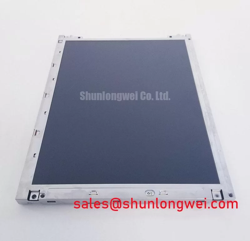
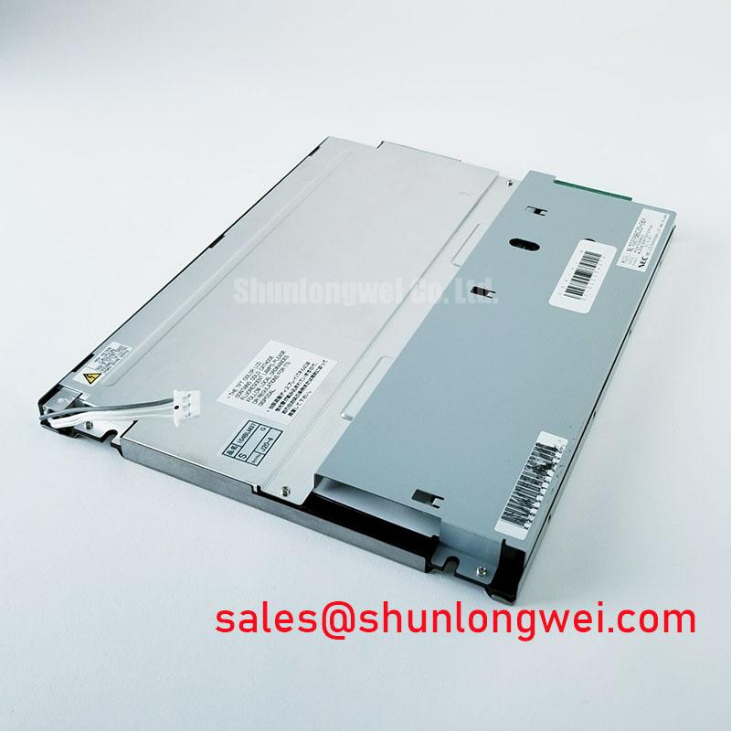
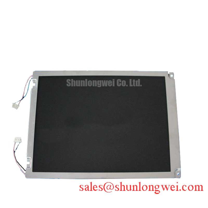
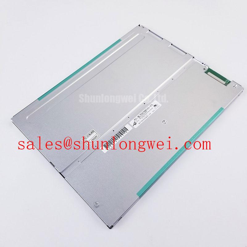
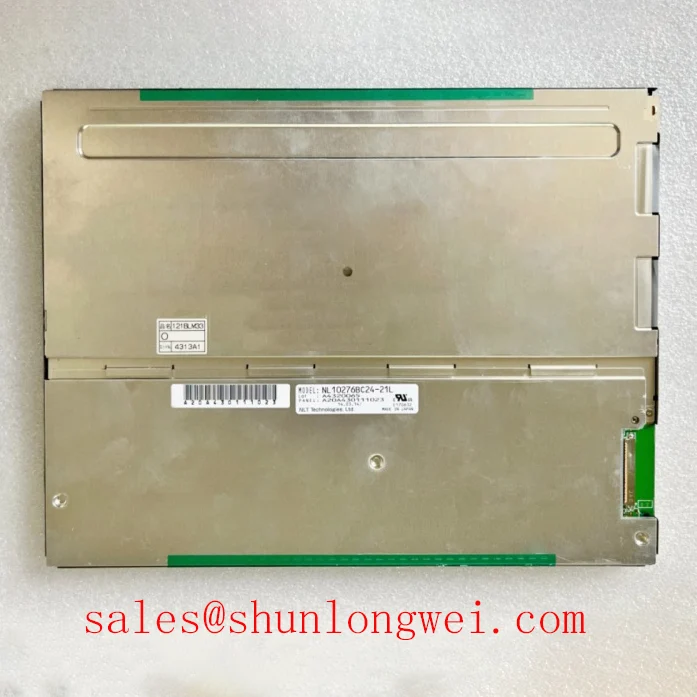
Begin incoming inspection by placing the NL10276BC24-21L face upward on a clean ESD-safe bench, then inspect the TFT-LCD Display Module perimeter for bezel distortion, corner pressure marks, damaged mounting features, and connector-area strain before it enters the machine enclosure. The available official factory information identifies this NEC unit as an Industrial Grade LCD/HMI Panel in a TFT-LCD Display Module enclosure. Interface type, outline dimensions, mounting-hole positions, supply requirements, backlight configuration, and optical ratings must be confirmed from the original panel documentation and the host equipment documentation before mechanical replacement work begins.
Metal operator-panel cutouts require special attention because an opening that appears visually correct can still impose stress as the enclosure, display bracket, gasket, and panel frame respond differently to temperature change. A display should sit in the intended mechanical datum without being forced into position by the mounting hardware. If the bezel bows after fastening, or if the active area changes appearance when individual fasteners are tightened, the assembly should be reviewed for uneven support, cutout interference, or localized pressure.
A cross-pattern tightening method is a useful Design Consideration when the panel is held by M3 hardware. A general industry starting range of 0.35 to 0.45 N·m is often used for M3 fastening where the mechanical drawing permits it, but it is not an NEC factory torque specification for this model. The final fastener selection, torque, washer arrangement, retention bracket, and gasket compression must be determined from the host mechanical design and verified against the applicable panel documentation.
💡 Bench Tip: Disconnect power, use ESD protection, and engage the display cable squarely and fully before closing any connector lock, because a skewed flex or cable insertion can create intermittent image faults that resemble a panel defect.
For a CNC operator panel or robot teach pendant, enclosure vibration and repeated service access can make connector retention as important as front-surface protection. Inspect the cable path for a smooth strain-relief route that does not pull on the display connector when the access door, pendant shell, or service panel is moved. Do not use the module connector as a structural restraint point.
Where the host system uses a differential display link, controlled routing is an Engineering Recommendation, not an official specification of the NL10276BC24-21L. Differential-pair impedance is commonly designed around 100 Ω ± 10%, with pair-to-pair timing alignment evaluated against the actual transmitter, cable, connector, and receiver requirements. In a high-noise factory cabinet, route display signaling away from servo motor cables, contactor wiring, switching power paths, and unshielded high-current conductors. Oscilloscope comparison with a known-good signal path can help distinguish an interface-integrity concern from a display-related issue.
Before assigning a replacement decision, compare the complete original assembly data: panel part number, connector position, mating cable, electrical interface, mechanical outline, mounting geometry, and system firmware expectations. Engineers evaluating a related NEC panel can review NL10276BC16-06 as a separate part-number reference, but no interchangeability should be assumed without a full document-to-document comparison.
Display Optical Uniformity and Thermal Buckling Prevention under Continuous Full-Duty Operation
Run a full-screen white, black, red, green, and blue test pattern after the module has stabilized in its intended enclosure. This simple sequence makes broad-area brightness variation, edge darkening, discoloration, pressure-related patches, and intermittent image behavior easier to identify than a normal application screen. Record any observation by screen location and repeat the inspection after the enclosure is assembled, since a clean image on an open bench does not by itself confirm that the mechanical installation is pressure-free.
The official information provided for NL10276BC24-21L confirms its industrial LCD/HMI classification, but does not state the backlight technology, luminance, contrast ratio, viewing-angle specification, anti-glare treatment, optical stack materials, thermal limits, or rated operating life. These properties should not be inferred from the TFT-LCD module category. The system integrator should verify the required optical and electrical information from the original panel documentation.
Continuous full-duty operation can expose thermal gradients created by the host enclosure, adjacent power electronics, a sealed front panel, or a rear bracket that conducts heat into only one side of the display. As a Design Consideration, support hardware should avoid concentrating force on narrow edges or creating a heat path that produces a visibly nonuniform active area. If an aluminum rail or other heat-spreading structure is used in the equipment, its placement should be validated at the assembled-system level to ensure it does not create mechanical loading on the display frame or obstruct the intended ventilation path.
Do not classify a contrast change under workshop lighting as a permanent panel issue before controlling the test conditions. Direct ambient light, a scratched protective window, polarized safety glasses, touchscreen overlays, and an uneven enclosure gasket can each affect perceived black level and color. A controlled test uses stable image patterns, a repeatable viewing direction, a clean front surface, and the same ambient lighting conditions for both the suspect screen and any known-good assembly.
For operator interfaces that remain powered for long shifts, check thermal behavior with the real front cover, control board, cable bundle, and power supply installed. An image that becomes uneven only after the cabinet warms may indicate a system-level thermal or mechanical interaction. The observation should be correlated with enclosure temperature, fastening sequence, nearby heat sources, and the condition of the display cable. It should not be assigned to an unverified internal material or internal panel structure.
Color and viewing behavior must also be evaluated from the operator’s actual position. The official information supplied does not identify the liquid-crystal mode or wide-viewing technology for this NEC part, so IPS, MVA, or any other display mode must not be assumed. If a replacement is considered for a CNC panel or teach pendant, compare the observed image from the normal operating angle, then verify the original optical requirements in the applicable documentation. A broader reference on panel selection and test terminology is available in The Ultimate Guide to Industrial TFT LCD Technology.
Mechanical Stress and Glass-Panel Fracture Prevention
Use a stable, supported work surface when handling the NL10276BC24-21L. Hold the module by permitted structural edges rather than pressing the visible display area, and avoid twisting the assembly while a cable is attached. A replacement panel may be electrically correct yet show defects after installation if the mounting bracket forces the module into a non-flat plane. This risk is particularly relevant when a portable teach pendant shell has worn locating features or when a CNC front door has been bent during service.
A practical primary-color bench routine begins with red, green, and blue full-screen patterns, followed by white and black. During each pattern, inspect for persistent lines, isolated bright or dark pixels, color-selective bands, broad patches, and image changes caused by gentle enclosure movement. These observations help create a repeatable record, but they do not prove a single internal cause. A line that remains fixed across several patterns may warrant comparison with a known-good display path, while a symptom that follows cable movement may justify checking connector engagement, cable condition, shielding, and host output timing.
A 45-degree flashlight check with a black test image can be useful when separating a visible image path from an illumination concern. If faint graphics remain visible under controlled external light while the expected illuminated image is absent, the result can guide further inspection of the system display chain. It does not identify a specific backlight technology or establish an internal failure mechanism. The official factory information supplied does not specify the backlight arrangement for this model.
Cold-area behavior should be assessed carefully. No official minimum operating temperature, response-time figure, or heater requirement has been provided for the NL10276BC24-21L. Therefore, claims about sub-zero response, grey-to-grey behavior, or a heater-strip control method would not be supported by the confirmed factory data. When equipment must operate in low ambient conditions, the system engineer should verify the original display environmental ratings and then test image response, startup behavior, and touch or overlay performance at the real equipment temperature.
Image artifacts can originate outside the panel itself. The timing controller function is often discussed in relation to grey-scale voltages, source signals, and gamma behavior, but the provided data does not disclose this module’s internal architecture. Field investigation should focus on measurable external evidence: correct input power from the original documentation, cable continuity, connector condition, host-board output behavior, image repeatability, and comparison against an established good assembly. This approach avoids replacing a display when the actual issue resides in the cable, controller board, power circuit, or front-panel mechanics.
Backlight High-Voltage Ignition and Driver Debugging
Do not assume that the NL10276BC24-21L uses dual-channel CCFL lighting, an LED driver, PWM dimming, or any particular inverter architecture. The official factory information confirmed here identifies the product as an NEC industrial TFT-LCD display module but does not provide a backlight type, lamp count, driver input, dimming method, ignition voltage, or operating-life rating. Those values must be obtained from the original panel documentation and the host display assembly documentation before any repair or replacement decision is made.
When the screen is dark, first establish whether the host system is producing the expected display content and whether the complete module supply and interface conditions match the original equipment requirements. Check the connector for incomplete insertion, inspect the cable for pinch damage or repeated flexing, and compare behavior with a known-good cable or panel assembly where available. A dim screen, blank screen, flicker, or audible noise can each arise from more than one part of the system, so a single visual symptom should not be treated as a definitive diagnosis.
If the original equipment documentation confirms a high-voltage lamp-based backlight circuit, use suitably rated test equipment and follow the host equipment’s electrical safety procedures. If the documentation confirms an LED-based arrangement, verify the driver enable, current-control path, and dimming command according to the system design. Neither architecture should be presumed from the panel name alone. Claims regarding a specific ignition range, PWM ratio, acoustic performance, L70 or B50 behavior, MTBF value, or service-life hours are outside the confirmed official data for this product.
In high-EMI industrial equipment, display instability may be associated with the whole signal path rather than a single panel. As an Engineering Recommendation, review cable shielding termination, chassis bonding, connector seating, and differential-pair continuity while observing the display during nearby servo, spindle, relay, or switching-power activity. The objective is to reduce coupled noise and verify peak signal margins through system testing, not to assign an EMC compliance claim to an individual LCD module.
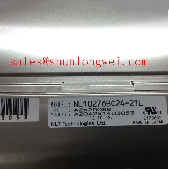
For maintenance records, retain photographs of each full-screen test pattern, the original label information, cable-routing condition, enclosure mounting state, and the observed symptom before and after reassembly. This evidence gives repair engineers and procurement teams a clearer basis for comparing the NL10276BC24-21L against the original installed unit while keeping the decision grounded in verified physical, electrical, and optical compatibility.