

Content last revised on September 13, 2026
Chassis Fastener Mounting to Evaluate Optical Mura Defects
The display module must sit flat against the host bezel and support structure without localized bending. A panel can remain electrically functional while an uneven clamping load introduces visible nonuniformity in dark images, gray fields, or low brightness operation. This effect is commonly described in service work as mura, although visual artifacts can have several origins and should be evaluated rather than assumed to be pressure related.
No NEC factory torque specification is established here for the NL6448BC33-71. Final torque, fastener length, washer arrangement, bezel geometry, and thread engagement must be determined from the original equipment mechanical drawing and the panel documentation. If the original display was mounted with a compressible gasket, a rigid frame, or a rear support rail, retain that arrangement as closely as practical during service evaluation.
Before mounting, place a straightedge across the host opening and look for raised paint, corrosion products, warped plastic, burrs, or displaced seals. A bezel that pulls one corner inward can create a local optical disturbance even when all screws appear equally tightened. Bring screws down gradually in a cross pattern so the module settles evenly. If a symptom becomes more apparent after fastening, release the fasteners carefully and compare the image again under the same input condition. That comparison can help distinguish mounting stress from timing, source, or illumination issues.
The available factory information does not establish an NEC backlight type, rated brightness retention, or a 50,000 hour brightness life figure for this model. It would therefore be inaccurate to assign an LED MTBF curve, an L50 point, or any backlight decay expectation to the NL6448BC33-71. In a complete display assembly, illumination aging is influenced by driver current regulation, thermal transfer, duty cycle, airflow, and operating profile. These are system conditions that should be checked at the equipment level rather than treated as panel specific ratings.
For repair planning, record the mounting arrangement before removal. Capture the locations of shields, grounding springs, edge tapes, spacer blocks, and cable retainers. These details are often essential to restoring the original mechanical and electromagnetic behavior. In applications such as industrial HMI stations or radar and navigation bridge console displays, enclosure sealing and marine environmental suitability remain responsibilities of the finished equipment assembly, subject to the original equipment requirements.
Where an alternative part is being evaluated, physical fit alone is not evidence of compatibility. The NL10276BC16-06 can be reviewed as a separate candidate, but engineers should compare its mechanical drawing, connector position, signal format, power sequence, optical performance, mounting arrangement, and controller compatibility against the original equipment documentation before any substitution decision.
Flashlight Dark-Shadow Optical Diagnostic to Isolate Logic vs. Backlight Failure Modes
When an installed screen appears black, begin by confirming that the host equipment has completed its normal boot and display enable sequence. Observe status indicators, controller alarms, touch response where applicable, and output behavior from the equipment. Then inspect the display cable at both ends for partial insertion, damaged locking features, strain at the bend radius, or contamination. A connector can appear installed while one side of a fine pitch contact row is not fully engaged.
A practical bench method is to present stable red, green, blue, black, white, and midgray images from a known good video source, provided the original interface and power conditions have been verified from the system documentation. Look for repeating vertical or horizontal lines, missing color contribution, intermittent image breakup, unequal areas of brightness, and image changes when the cable is lightly supported rather than pulled. These observations do not prove a particular internal failure mechanism, but they help separate a source path concern from an optical symptom.
A flashlight held at an oblique angle can be useful when the panel face seems unlit. With the system displaying a known image, direct light across the front surface at roughly forty five degrees and look for faint image structure. If a dim image becomes visible, the evidence may point toward an illumination path or display enable condition rather than a complete absence of image data. It does not independently establish the condition of a backlight circuit, controller, or panel assembly. Compare with a known good signal path and use appropriate instruments before replacing parts.
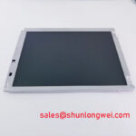
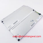
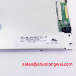
The factory information supplied for the NL6448BC33-71 NEC TFT LCD Display Module does not specify its native signal interface. Do not assume LVDS, TTL, eDP, a differential impedance target, pin order, clock polarity, or supply voltage. The system integrator should verify the required supply voltage and interface definition from the original panel documentation. If the interface is documented as differential, signal integrity is a Design Consideration: maintain the original cable routing and shielding, minimize unnecessary cable changes, and verify waveform quality against the known good signal path with suitable test equipment.
Noise from servo drives, contactors, inverter cables, and switching supplies can enter the display system through cable routing or the host ground structure. The panel itself should not be described as independently compliant with a system EMC standard. For a machine that shows intermittent image corruption near high power operation, inspect shield terminations, connector retention, cable separation, chassis bonding, and the controller output before drawing conclusions about the panel.
Grey scale irregularities can also originate upstream. The host timing controller and image source establish pixel data, clocking, and panel control relationships. An image that has changed in one operating mode but remains stable on another input can indicate a controller or source configuration issue. A persistent defect that remains with the same panel after the input path has been verified may justify further panel level evaluation, but it should not be described as a confirmed internal driver fracture without supporting evidence.
For broader diagnostic context on panel interfaces, optical behavior, and common integration checks, review The Ultimate Guide to Industrial TFT LCD Technology alongside the original equipment service documents.
Thermal Cycling Degradation of Polarizer Adhesives & Sealant Gasket Integrity
Thermal behavior should be assessed at the installed assembly level. The available factory information does not confirm an operating temperature range, low temperature response time, polarizer construction, perimeter sealant formulation, gasket design, or heater compatibility for the NL6448BC33-71. It is therefore not appropriate to claim that this NEC model is qualified for −30°C to +85°C cycling, to publish a Gray to Gray response figure, or to state a specific sealant durability result.
In cold field conditions, liquid crystal displays can show slower apparent transitions, reduced contrast, or temporary visual changes. Such behavior may be associated with temperature, but it can also be influenced by the video source, power sequencing, cable condition, and illumination level. If the symptom occurs only after a cold start, document ambient conditions, warm up behavior, controller status, and input image performance. That record is more useful than assigning a cause based on appearance alone.
Where the equipment uses an enclosure heater or controlled cabinet temperature, its set point and activation strategy are determined by the equipment designer. A Design Consideration is to prevent abrupt local temperature differences between the display face, rear metalwork, and surrounding enclosure. Verify that any heater does not obstruct ventilation, overload the host supply, create a local hot area, or interfere with the original cable path. The display panel should not be used as a temperature sensor unless the original system specifically provides that function.
During removal, inspect the perimeter between display, bezel, and enclosure for hardened residue, displaced foam, trapped salt deposits, moisture evidence, or corrosion on external hardware. These observations can indicate that the host enclosure needs attention, especially where the equipment operates near moisture, airborne contaminants, or large temperature swings. They do not establish the condition of internal seals that are not accessible without destructive analysis.
For installations evaluated for navigation bridge or outdoor industrial terminals, sunlight, salt exposure, condensation, enclosure ingress protection, and vibration are finished system concerns. Engineers should verify the original assembly requirements and retain specified covers, drains, shields, and seals. No independent marine, environmental, optical sunlight, or ingress rating is asserted here for the NL6448BC33-71.
Suppressing Localized Thermal Gradients to Prevent Chronic Optical Yellowing (Color Shift)
Check the rear of the installed display for nearby heat sources before attributing color shift to the LCD module. Power converters, CPU boards, LED driver circuits, radiant process heat, restricted fan paths, and a blocked rear cover can create uneven temperatures across an HMI assembly. A color change that follows equipment warm up may be associated with thermal conditions, but comparison against a stable reference image and known good unit remains important.
The supplied official information does not identify the internal optical materials of the NL6448BC33-71, so no claim can be made about PMMA construction, anti glare treatment, contrast ratio above 500:1, direct sunlight performance at 50,000 lux, or a defined L70 or B50 backlight lifetime. Those values must not be used as specifications for this NEC panel without the corresponding factory datasheet.
As an Engineering Recommendation, retain clear airflow where the original equipment provides it and avoid concentrating heat at narrow display edges. If an aluminum spreader rail is part of the original chassis, reinstall it with the original interface arrangement and verify that it does not apply bending force to the display. Any change to heat spreading, fan control, or enclosure ventilation should be validated by the system engineer under the actual electrical load, ambient condition, and image duty cycle.
Use uniform test patterns after reassembly. A full white image helps reveal brightness variation and color imbalance, while dark gray and black patterns can reveal pressure marks, edge leakage, or contamination on the optical stack. Check the screen from the normal operator position and from off axis angles relevant to the equipment layout. Viewing angle behavior, contrast retention, and color shift are panel specific characteristics that require the original NEC documentation for a formal acceptance criterion.
For urgent replacement work, preserve the original cable dress and strain relief, confirm connector orientation before power up, and verify the image during a controlled warm up period. This procedure provides a defensible record of the panel condition, host interface behavior, mounting result, and thermal environment without assigning unsupported ratings to the display module.