Content last revised on October 20, 2026
NL6448AC33-18J Replacement and Integration Checks
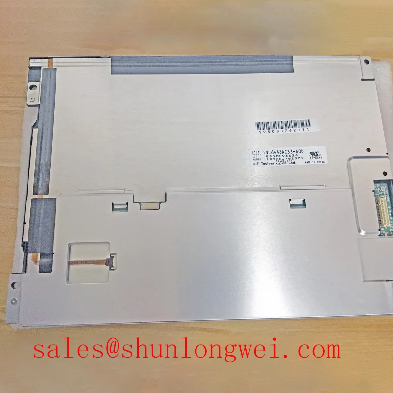
Check the display label, cable orientation, and mounting clearances before connecting a replacement NL6448AC33-18J; a matching connector shell does not establish electrical compatibility. This NEC TFT-LCD active matrix color display module belongs to the industrial LCD/HMI panel category. A useful replacement assessment separates the panel itself from the host controller, backlight power circuit, protective window, and any independently fitted touch interface.
For the NL6448AC33-18J product reference, establish a compatibility record containing the complete model suffix, connector assignments, mechanical drawing, display timing, and backlight interface. Preserve the original cable routing and mounting stack during initial inspection. Changing several interfaces together makes it harder to distinguish a panel fault from an integration problem.
Assessing Localized Thermal Gradients and Persistent Optical Yellowing (Color Shift)
Compare surface temperature patterns with the location of any persistent color shift before modifying the enclosure or display supports. As a Design Consideration, uneven heat exposure can affect optical appearance, but discoloration alone does not identify the affected layer or establish a single failure mechanism. Compare uniform test images at consistent brightness, viewing angle, and warm-up condition, then inspect the protective window separately from the display surface.
Evaluate nearby power components, restricted airflow, and contact between the display frame and enclosure. An aluminum heat-spreading rail is an enclosure-level option, not a documented feature of the NL6448AC33-18J. Its geometry should follow measured heat distribution and available mounting surfaces. Avoid transferring concentrated mechanical loads into the display frame while attempting to improve thermal contact; mounting distortion can introduce visible nonuniformity that complicates the original diagnosis.
Do not attribute yellowing to a particular internal light-guide material or apply an LED lumen-maintenance classification to this model without supporting manufacturer documentation. Optical aging, backlight output reduction, and electronic reliability describe different behaviors. A useful service record instead captures image appearance, brightness settings, ambient conditions, and whether the symptom changes when external illumination or enclosure temperature changes.
For broader terminology, The Ultimate Guide to Industrial TFT LCD Technology provides background for organizing an integration review. The Tianma industrial display resource provides industrial-display context; neither general resource substitutes for a model-specific electrical or mechanical specification.
Assessing Frame Lag & Image Smearing in Low-Temperature Industrial Environments
Separate delayed pixel transitions from delayed image delivery by comparing a moving test pattern with the host controller’s update behavior. As a Design Consideration, liquid-crystal response generally becomes slower as temperature decreases. That mechanism does not establish a cold-operation rating for this panel, and storage exposure must not be treated as permission to operate at the same temperature.
Evaluate environmental suitability against the panel’s specified operating and storage limits before conducting temperature testing. Record whether smearing affects all transitions or particular grayscale changes, and distinguish it from dropped frames, unstable synchronization, or software refresh delays. Use the same image source for comparisons so that changes in the controller do not obscure changes in panel response.
Backlight modulation requires a separate check. Compare brightness stability with the actual driver’s control input and output behavior rather than assigning a generic PWM frequency. If an external constant-current LED driver forms part of a documented conversion assembly, assess dimming linearity, low-brightness stability, and protection behavior at that assembly level. Those characteristics must not be transferred to the original NEC module as factory specifications.
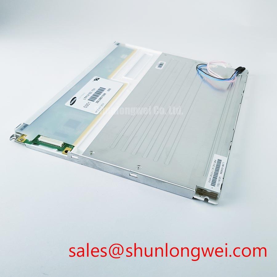
For replacement sourcing, the NL6448BC33-71 can be included in a separate comparison, but a related NEC part number is not evidence of interchangeability. The following checks keep the two model identities distinct.
| Comparison item | NL6448AC33-18J | NL6448BC33-71 |
|---|---|---|
| Manufacturer | NEC | NEC |
| Role in this assessment | Target TFT-LCD active matrix color display module | Separate model for compatibility assessment |
| Dimensions, active area, and mounting points | Consult model-specific mechanical drawing | Compare against target drawing |
| Resolution, signal interface, and connector assignments | Consult model-specific datasheet | Verify individually before substitution |
| Supply, backlight, timing, and temperature limits | Consult model-specific datasheet | Compare complete operating requirements |
A substitution decision should account for the complete host interface, not just the visible image area. Retaining an existing cable or backlight power unit is appropriate only after its electrical assignments and operating requirements match the replacement assembly.
Grayscale Inversion Assessment & Optimal Viewing Direction Alignment
Display a grayscale ramp and inspect it from the intended operator position before fixing the bezel orientation. As a Design Consideration, viewing-angle-dependent contrast can make adjacent gray levels difficult to distinguish even when the controller delivers the correct image.
Compare the same ramp above, below, and beside the intended viewing axis. Record whether the change follows viewing position or remains fixed within the image. This distinction helps separate angular optical behavior from image-processing errors or localized pressure effects. Do not assign viewing-cone figures from an IPS or MVA panel to this model, or assume that a different panel technology will preserve the original mechanical and electrical interface.
Under strong ambient illumination, inspect reflections from both the panel and the enclosure window. Anti-glare treatment can spread reflected light, while anti-reflection treatment addresses reflected intensity through a different optical approach. Neither treatment should be claimed as an NL6448AC33-18J feature without a corresponding specification. Evaluate readable contrast with the actual window, lighting direction, and operator position rather than relying on an isolated brightness claim.
When evaluating this module for a precision electronic test and measurement instrument, designers should verify that fine traces, small labels, and status colors remain distinguishable through the assembled front window. Any added touch overlay requires its own mechanical and controller assessment. Glove operation and wet-surface behavior belong to the complete touch system, not to the underlying LCD panel designation.
Allow clearance for the display frame, connector access, cable movement, and enclosure tolerances. A bezel that presses against the active region can alter the image locally; compare the display before and after final fastening to identify assembly-induced changes.
Signal Interface Verification and Cable Routing for Stable Image Timing
Identify the panel’s actual signal interface from its connector assignment before applying differential-routing rules. Differential impedance is relevant only where the documented link uses differential signaling, and its target must follow the applicable transmitter, receiver, cable, and interface requirements.
As an Engineering Recommendation, compare the host schematic and cable continuity against the panel pinout before evaluating clock quality. For a documented differential link, maintain pair continuity and an appropriate return environment through connectors and flex transitions. For a documented parallel interface, evaluate clock-to-data timing and return paths instead. JEIDA/VESA mapping checks apply only where the implemented interface uses those conventions.
Pro Tip: When a differential interface is confirmed, control pair-to-pair timing and connector transitions together, then validate the received clock and data relationship on the assembled system.
Assess supply rise behavior, signal enable, and backlight enable against the model-specific power sequence rather than importing timing limits from another display. During intermittent-image troubleshooting, correlate supply disturbances with synchronization loss and controller activity. Split images, color errors, and unstable edges can have several origins; compare test patterns and measured signals with a known-good path before attributing the symptom to the panel.
Inspect cable strain and bend placement with the enclosure fully assembled. A cable that works on an open bench can experience different stress or coupling after installation. If the backlight shuts down, use the actual driver documentation to interpret any fault output and distinguish an open-load response, short-circuit protection, or supply interruption. Finish the integration check by confirming stable image timing, correct grayscale order, and consistent illumination with the final cable routing and mounting arrangement.