Content last revised on September 26, 2026
Optical Luminance Degradation Curve and CCFL to LED Modernization Retrofit Pathways
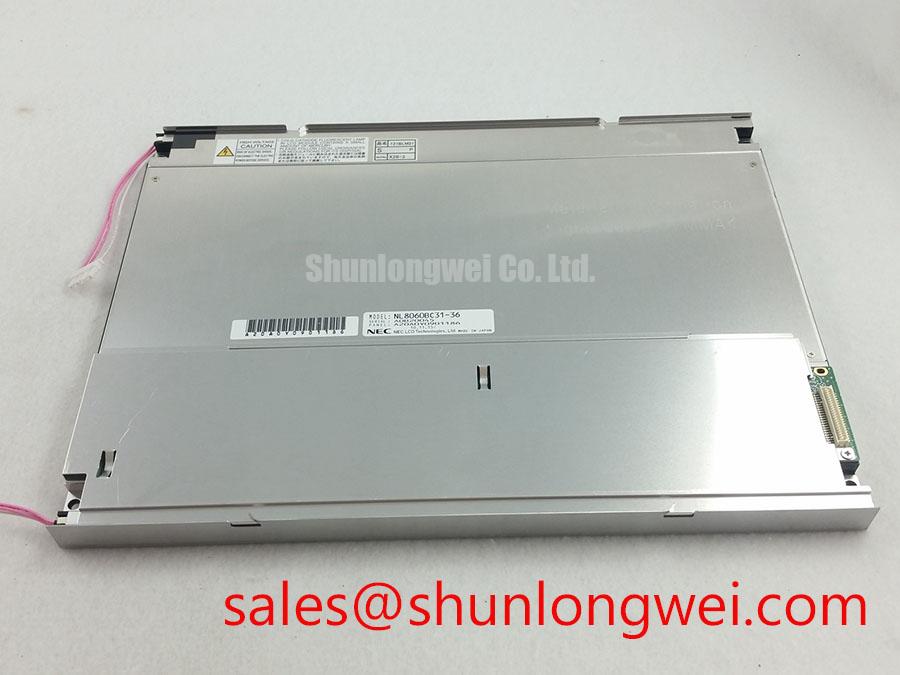
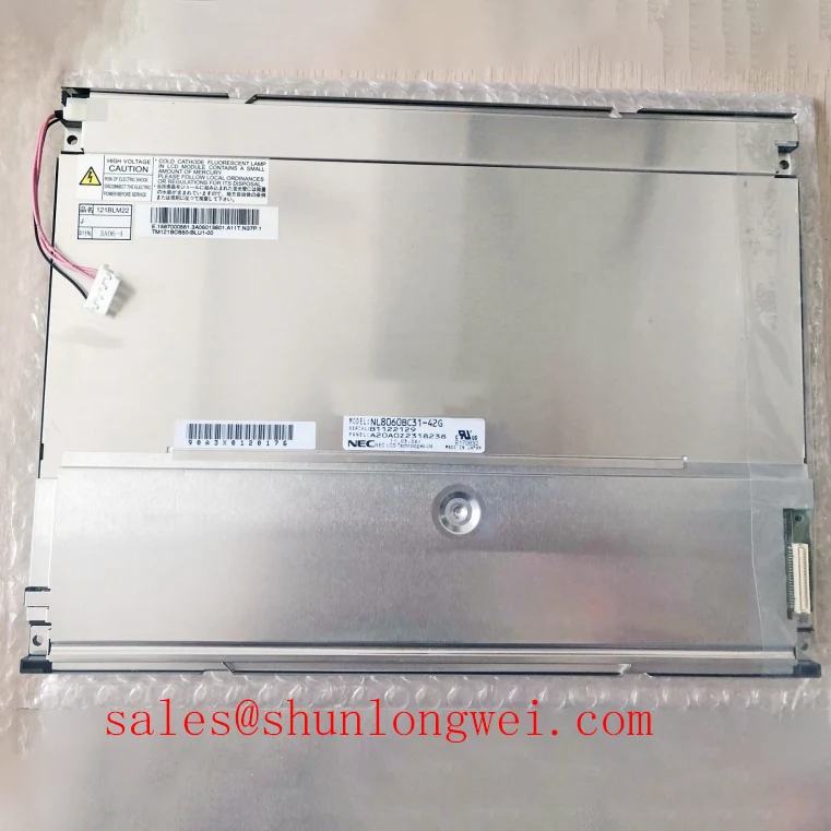
Begin incoming inspection by checking the NEC NL8060BC31-20 against the equipment service record, confirming the printed model identification, examining the TFT-LCD display module for edge impact or glass damage, and recording the panel condition before power is applied. The available factory identification classifies this part as an Industrial Grade LCD/HMI Panel with a TFT-LCD Display Module construction. The available product data does not confirm a backlight type, luminance rating, supply voltage, connector assignment, operating temperature range, or optical half-life, so those values should be verified from the original panel documentation before any retrofit decision.
For an AGV or forklift telematics display, optical inspection should be performed with a uniform full-screen image and with the enclosure in its normal mechanical orientation. Check for luminance differences near the panel edges, uneven dark areas, visible bright spots, color drift, and regions that change appearance when the display warms. A cold-start observation is useful because a display that appears acceptable after several minutes may show delayed illumination, unstable brightness, or uneven response immediately after energization. Record the ambient condition and the time required for the image to become stable rather than assigning the symptom to a single component without measurement.
A CCFL-to-LED modernization project must be treated as a system compatibility exercise, not as a direct lamp substitution. The integrator should verify the original backlight interface, ignition behavior, current-control method, dimming signal, connector polarity, mechanical clearance, optical coupling, and electromagnetic behavior. A constant-current LED driver can require a different enable sequence and control signal from the original panel electronics. The display documentation should also be checked for the permitted backlight supply and brightness-control method. The system integrator should verify the required supply voltage from the original panel documentation.
The high-voltage ignition values and long-term half-life figures specified in the proposed retrofit brief are not confirmed in the available factory data for this model. They should not be presented as product ratings for the NL8060BC31-20. The same limitation applies to any claimed LED lifetime, MTBF, PWM dimming ratio, or guaranteed acoustic-noise performance. Those characteristics belong to the selected backlight assembly and driver combination and require component documentation or measured validation.
When investigating an optical problem, first separate the panel image path from the backlight path. A stable image that is only visible under an external light source can point toward a luminance or backlight circuit issue, while image content that is missing or distorted requires signal-path inspection. Measure the known-good signal path with suitable equipment and compare startup behavior, enable timing, and brightness-control activity. Do not apply an unverified replacement driver to the original panel connector.
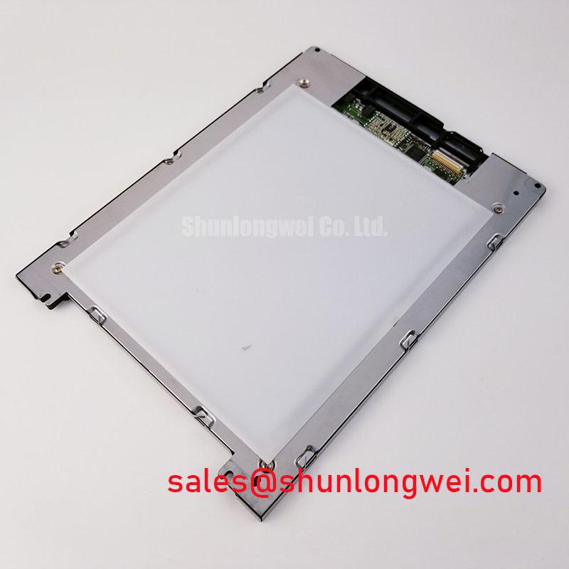
For a replacement evaluation, the same-size or same-resolution requirement should be confirmed from the host equipment drawing and the original display label. The linked NL10276BC16-06 may be reviewed as a separate compatible-device candidate, but connector assignment, mounting geometry, optical characteristics, and electrical timing still require system-level verification before ordering or installation.
Single Vertical Hairline Defect and Sub-Pixel Column Driver Open-Circuit Localization
Start a pixel inspection with a full-screen white field, then repeat the test with red, green, blue, black, and mid-gray fields. This multi-pattern check helps distinguish a constant pixel defect from a defect that becomes visible only against a particular color or luminance level. Inspect the image from the normal operator position and at an oblique angle, because a narrow line may be less apparent during ordinary operation than during controlled QA inspection.
A single vertical hairline can arise from several points in the display chain, including image data transmission, connector contact, panel glass circuitry, or the column-driver region. The visual symptom alone is not sufficient to identify the cause. First reseat the approved cable with power removed, inspect the connector for contamination or uneven engagement, and compare the signal behavior with a known-good display path. If the line remains fixed at the same pixel location across all input images, the result should be documented as a panel-side symptom requiring further technical assessment rather than described as a confirmed internal fracture.
A flashlight inspection at approximately forty-five degrees can be useful during a dark-screen check. It may reveal whether liquid-crystal modulation is present while the backlight is disabled, but it does not prove the condition of any internal bonding interface. Avoid pressing the active area or narrow edges during this test. Mechanical pressure can introduce a new intermittent symptom and can make later comparison unreliable.
The available factory information does not provide a confirmed TTL or LVDS interface definition, transmitter clock tolerance, data hold-time specification, cable impedance, or temperature timing table for the NL8060BC31-20. Engineers should therefore obtain the original interface documentation before probing or adapting the cable. If the host uses differential signaling, compare pair activity, common-mode behavior, and clock-to-data relationship with the known-good assembly. Any suspected timing margin issue should be evaluated over the actual equipment temperature range using the approved transmitter and receiver limits, not a generic display assumption.
Connector reliability deserves the same attention as optical inspection. The flexible cable should enter the connector squarely, with its exposed contact area fully aligned and the locking mechanism closed evenly. Avoid folding the cable sharply at the connector exit or allowing the enclosure cover to press directly on the flex. For an AGV or forklift display exposed to vibration, provide a controlled cable path and strain relief so that movement is absorbed by the harness support rather than transferred into the connector.
💡 Bench Tip: Use ESD protection, disconnect power before handling the display cable, and close the connector lock only after the flexible cable is fully parallel with the connector body.
Aluminum Heat Spreader Sizing and Thermal Interface Placement along Narrow Display Edges
The NL8060BC31-20 is identified as a TFT-LCD display module, but the available factory data does not specify a permitted heat-spreader material, edge temperature limit, thermal resistance, or mechanical compression range. Any aluminum rail or thermal interface should therefore be treated as a Design Consideration, not as a required factory feature. Its purpose should be defined by measured heat distribution, enclosure airflow, nearby electronics, and the mechanical structure of the finished HMI.
During a thermal evaluation, map the display assembly after cold start and after the equipment has reached its normal operating condition. Compare the narrow edges, connector area, backlight region, and adjacent controller hardware. A localized warm area does not automatically demonstrate a panel defect; it may reflect the driver board, backlight electronics, enclosure conduction, or an uneven contact surface. Use the measured results to determine whether heat spreading is needed and whether the proposed rail could create unwanted stress on the glass or frame.
A heat spreader should not obstruct the active area, interfere with the connector, or force the panel against an uneven chassis. The interface should be continuous enough to avoid isolated pressure points, while the mounting arrangement should allow for manufacturing tolerance and differential expansion. Designers should verify the contact pattern with a non-damaging fit check before final assembly. Avoid adding adhesive, pads, or fasteners that have not been checked for thickness, outgassing, electrical clearance, and long-term mechanical behavior.
PWM frequency and duty-cycle linearity are system-level properties unless the panel documentation explicitly defines them. The available specification context does not confirm a PWM range for this model. If the replacement backlight uses PWM, the controller designer should verify the accepted logic level, frequency window, minimum pulse behavior, startup sequence, and visible flicker performance under the intended camera and operator conditions. Audible noise should be checked at the complete assembly because it can originate from the driver, mounting structure, or enclosure resonance.
For cold-start evaluation, measure image availability and luminance response from the actual minimum equipment temperature rather than extrapolating from room-temperature operation. Liquid-crystal response, backlight startup, cable flexibility, and controller initialization can each affect the observed delay. If the AGV or forklift control system expects a display-ready signal within a defined interval, the integrator should verify that sequence using the host controller and the original panel documentation. A software delay or controlled startup state may be preferable to applying an unverified electrical modification.
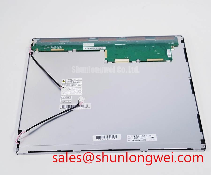
Potential mechanical compatibility should also be reviewed with the wider display solution. The linked NL10276BC30-24D can be examined as a related display solution for system architecture comparison. It should not be treated as an automatic electrical or mechanical companion for the NL8060BC31-20 without confirmation of the host interface, backlight arrangement, mounting features, and control requirements.
Dynamic Contrast Stabilization and Liquid Crystal Temperature Tracking
Contrast evaluation should begin with black, white, and mid-gray test patterns viewed under the lighting conditions expected at the equipment operator position. Record whether the image remains readable when ambient light changes, when the enclosure cover is fitted, and when the display transitions from a cold state to normal operation. The available factory information identifies the product category and module construction but does not confirm a contrast ratio, viewing angle, anti-glare treatment, liquid-crystal mode, or temperature compensation profile.
Do not classify the NL8060BC31-20 as TN, IPS, or MVA without a verified manufacturer data sheet. Those display technologies have different viewing behavior, grayscale response, and temperature characteristics. A change in gray level at an angle can be related to the panel mode, optical stack, cover glass, surface treatment, or image-processing settings. The correct evaluation method is to compare the replacement panel with the original unit using the same test image, viewing position, ambient illumination, and controller settings.
In a rugged telematics enclosure, a cover window can alter perceived contrast through reflection and glare even when the LCD itself is operating correctly. The system integrator should verify the cover material, spacing, sealing arrangement, surface finish, and cleaning method as part of the complete optical path. A display that looks acceptable on the bench may require a different luminance setting once installed behind a protective window.
Temperature tracking should include cold startup, stabilized operation, and the transition between those conditions. Observe grayscale uniformity, response delay, flicker, line defects, and any change in the visibility of previously recorded pixel anomalies. If the host controller changes timing or backlight control during startup, capture the relevant signals and compare them with the approved interface requirements. Clock jitter, data hold time, and link margin must be verified from the actual transmitter, cable, receiver, and panel documentation; generic TTL or LVDS values cannot be assigned to this model without evidence.
FPC reliability remains important during temperature cycling and vibration. The flex should be routed without a sharp fold at the connector, kept clear of screw heads and enclosure edges, and supported so that repeated vehicle movement does not pull on the contact region. Designers should validate the installed assembly through the equipment’s own vibration and thermal test plan. These tests assess the complete mounting system rather than proving an unlisted internal construction feature of the display module.
Additional integration guidance for industrial HMI assemblies is available in the Industrial Display & HMI Solutions reference area. For purchasing and incoming QA, retain the model identification, connector documentation, optical test records, installation photographs, and host-equipment compatibility findings with the service file for each evaluated NL8060BC31-20 display.