

Content last revised on September 12, 2026
LB084S01-TL01 Overview
At incoming inspection, place the LB084S01-TL01 on an ESD-safe bench, check the module label against the purchase record, inspect the glass and frame for transport damage, and verify the connector area before applying power.
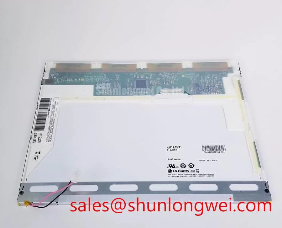
The LB084S01-TL01 is identified in the supplied factory information as an Industrial Grade LCD/HMI Panel manufactured by LG Display. Its package form is a TFT-LCD Display Module, and its specification status is recorded as Official Factory Spec Verified. The available product data does not establish a complete electrical pinout, resolution, luminance rating, viewing angle, backlight type, operating temperature range, or interface voltage. Those values should be confirmed from the original panel documentation before system integration.
| Model | LB084S01-TL01 |
| Manufacturer | LG Display |
| Product category | Industrial Grade LCD/HMI Panel |
| Package or enclosure | TFT-LCD Display Module |
| Specification status | Official Factory Spec Verified |
For repair engineers, the most important first decision is whether the replacement matches the original electrical and mechanical interface. Compare the mounting points, active display area, connector orientation, cable reach, frame clearance, and optical stack position. A panel with the same nominal diagonal size may still require a different controller, cable assembly, backlight driver, or mounting bracket. The system integrator should verify the required supply voltage from the original panel documentation rather than infer it from a visually similar display.
Thermal and Optical Assembly Preservation
The supplied information does not verify that the LB084S01-TL01 uses an edge-lit LED rail, a PMMA light guide plate, or a particular luminance class. These construction details should therefore be treated as assembly-level items requiring confirmation from the original technical drawing or service documentation. During inspection, look for uneven illumination near the display perimeter, localized discoloration, pressure marks, and signs that the frame has been distorted during removal.
As a Design Consideration, any external heat spreader or frame modification should preserve the manufacturer’s mechanical clearances and must not press against the glass, optical films, diffuser layers, or cable exits. Thermal improvements should be evaluated by measuring the temperature distribution across the operating assembly rather than by attaching metal directly to an unverified optical or electrical surface. The backlight current, dimming method, and driver compatibility remain system-determined items.
When this panel is evaluated for telematics displays in heavy mining shovels or earthmoving equipment, enclosure airflow, vibration isolation, sunlight exposure, and service access should be reviewed together. The module itself should not be assigned a field lifetime or brightness-retention value without a supporting LG Display specification or qualified test report. A replacement assessment should compare the known-good panel and the candidate panel under the same image, backlight, and thermal conditions.
Low-Temperature and Outdoor Industrial Display Evaluation
Liquid-crystal response changes with temperature, but the supplied factory data does not confirm the LB084S01-TL01 operating temperature limits, gray-to-gray response time, sealant construction, or low-temperature performance. For equipment stored outdoors or exposed to cold environments, allow the panel and electronics to reach a controlled temperature before judging image behavior. Check whether the perceived smear is present in the panel itself, the display controller, the video source, or the cable path.
A practical evaluation uses moving test patterns, text scrolling, grayscale transitions, and a known-good signal chain. If the image becomes unstable, compare the input waveform and timing at the panel interface with the original assembly. The system integrator should verify interface signaling, clock frequency, data polarity, timing margins, and power sequencing from the panel documentation. Do not assume that a controller configured for another 8.4-inch class display is electrically compatible.
Backlight modulation also requires confirmation. The available product information does not specify PWM frequency, duty-cycle linearity, or whether brightness control is implemented through PWM, analog current control, or another method. If visible flicker or audible driver noise is observed, inspect the backlight driver and control waveform with the panel connected under normal load. Any proposed dimming change should be validated for brightness uniformity, camera compatibility, and signal stability across the intended temperature range.
Front-Surface and Optical Inspection under Direct Industrial Lighting
Inspect the front surface under diffuse and directional lighting before energizing the module. Record scratches, coating marks, edge lifting, pressure shadows, and nonuniform reflections. A full-screen white, black, red, green, and blue sequence helps separate surface contamination from pixel defects. Use a controlled viewing position and consistent illumination so that dust, mura, and genuine pixel anomalies are not recorded inconsistently.
The supplied factory parameters do not confirm the polarizer construction, anti-glare treatment, optical retardation film, LCD mode, or viewing-angle specification of this model. Do not describe the panel as TN, IPS, or MVA without a supporting manufacturer document. Likewise, a symmetric viewing cone or a particular contrast ratio cannot be assigned to the LB084S01-TL01 from the information available here.
For direct industrial lighting, assess readability with the actual protective window, bezel, and enclosure installed. Reflections may originate from the panel surface, cover lens, air gap, or surrounding frame. Optical changes should be judged using the complete assembly because an external anti-glare layer can alter contrast and color appearance. If the display is intended for a rugged operator station, verify that the mounting method does not create localized pressure on the glass.
Signal integrity inspection should begin at the source and continue through the cable and connector. The exact TTL or LVDS interface, pin assignment, clock relationship, and data hold requirements are not confirmed in the supplied data. Confirm these values from the original panel documentation, then inspect connector seating, cable alignment, shielding, and strain relief. 💡 Bench Tip: Protect the panel with ESD controls and lock the display cable fully square to the connector before applying power.
Backlight Driving, Dimming, and Flicker Evaluation
The LB084S01-TL01 product information supplied here does not verify a WLED backlight, constant-current driver, 1000:1 dimming capability, CCFL circuitry, or a specified half-life. These features must not be treated as factory parameters for this model without a matching datasheet. Before selecting a replacement driver, identify the original backlight architecture, connector wiring, current regulation method, enable signal, and protection behavior.
When a compatible LED backlight is confirmed by the original documentation, the driver should be evaluated for current stability, startup behavior, dimming response, and thermal performance. Flicker testing is best performed with both a photometric instrument and a high-speed electrical measurement because visual inspection alone can miss modulation-related problems. If the panel is connected to a machine camera or optical sensor, evaluate the camera image at the selected brightness settings.
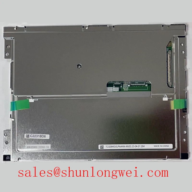
For maintenance teams, replacement work should include a connector and cable inspection, a clean power-up sequence, and a comparison against the original display using identical controller settings. Any abnormal line, color, brightness, or timing behavior should be traced through the complete display chain rather than assigned to the panel without measurement. Engineers comparing an alternative industrial LCD should review the documented interface and mechanical data for TCG084SVLQAPNN-AN30-S as a separate selection exercise, not as an automatic substitute.
For background on TFT-LCD operating principles, interface considerations, optical behavior, and common selection errors, consult The Ultimate Guide to Industrial TFT LCD Technology. Final compatibility remains dependent on the original equipment documentation, controller configuration, mounting arrangement, and measured behavior of the complete display assembly.