

Content last revised on November 5, 2026
Full-Screen Primary Color AOI Screening: Stuck Sub-Pixels & Background Uniformity Audit
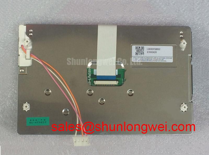
I display full-screen red, green and blue patterns through a compatible controller, keeping the image source and backlight setting unchanged throughout the inspection. For the Sharp LQ080Y5DR02, this establishes a repeatable starting point for separating persistent sub-pixel anomalies from content-dependent artifacts. Record each visible defect by position and color response, then compare the observations with the applicable panel acceptance criteria.
Design Consideration: Follow the primary colors with white, gray and black screens to examine background uniformity, edge shading and persistent lines. Keep the viewing position and ambient illumination consistent. A photographed bright patch can change with camera exposure or viewing angle, so compare the live image before treating it as an assembly defect. Repeat the observation with a known-good image source where practical.
For a dark screen, illuminate the surface obliquely while displaying a recognizable pattern. A faint visible image supports further investigation of the illumination path, but does not establish a specific failed component. Persistent lines also require comparison of the source, cable and panel connections; their appearance alone cannot establish an internal driver fracture. Avoid pressing the glass or bonded edges as a diagnostic shortcut.
Design Consideration: If inspection occurs after cold storage, allow the assembly to stabilize within its specified operating conditions before judging motion performance. Liquid-crystal response can slow as temperature falls, making transitions appear smeared. Any enclosure heating belongs to the equipment thermal design and requires validation against the panel temperature limits, sensor placement and local temperature distribution.
Suppressing Acoustic Capacitor Buzz & EMI Emissions during PWM Dimming
Correlate audible noise with the backlight command, driver input current and displayed brightness before changing the dimming configuration. Design Consideration: PWM modulation can excite mechanical vibration in components on the driver board, while supply ripple can produce brightness modulation. Comparing these observations helps distinguish an acoustic issue from an unstable illumination output without attributing either symptom automatically to the LQ080Y5DR02.
Evaluate the installed illumination circuit from its schematic and component documentation. Where constant-current regulation is used, inspect current stability and driver temperature across the intended dimming range. The equipment designer should select modulation behavior from the supported control interface and validate low-brightness operation, camera interaction and audible behavior in the assembled enclosure. Driver efficiency depends on the complete conversion circuit and its operating conditions.
Check documented fault outputs alongside the enable command and illumination response. An open-load or short-load indication can guide inspection of connectors, wiring and the load, but its meaning depends on the driver implementation. Overvoltage protection thresholds, fault recovery and shutdown behavior belong to that driver specification. Repeatedly cycling a faulted circuit provides less useful evidence than capturing its startup response and protection status.
For viewing under strong ambient light, assess the complete front assembly with representative screen content. Design Consideration: Anti-glare treatment redistributes reflections, while anti-reflection treatment reduces reflection through a different optical mechanism; neither treatment should be attributed to this model without its surface specification. Include the protective window and air gap in the assessment. For the distinction between brightness depreciation and reliability metrics, consult The Ultimate Guide to Industrial TFT LCD Technology; a backlight depreciation endpoint and MTBF describe different outcomes.
Radiated Emissions Assessment: Backplate Grounding & Cable Shield Termination
Observe image stability while the surrounding equipment changes operating state, and record whether disturbances follow cable movement, drive activity or dimming commands. Design Consideration: Horizontal bands and unstable pixels can involve different coupling paths. Compare the display supply, video link and chassis connections under the same operating conditions before assigning the disturbance to a grounding fault.
Review how cable shielding terminates at the enclosure and how the display backplate connects to the equipment chassis. Shield continuity and short bonding paths can influence common-mode current, but a star arrangement or multiple connections cannot guarantee a favorable result in every enclosure. Select the bonding arrangement from the equipment grounding architecture and confirm its effect through measurements. Cable shield termination also depends on the actual connector construction.
Engineering Recommendation: Where a differential interface is documented, preserve pair symmetry and the intended return path through connectors and cable transitions, then validate signal quality at the receiving end.
Ferrites and other suppression components should address a measured coupling path, with signal integrity checked after any change. CISPR or other applicable emissions assessment concerns the assembled equipment, its ports and its operating configuration; it does not establish an independent compliance claim for this display module. Manufacturer resources such as Sharp Devices Europe Industrial Display Solutions provide display technology context, while acceptance limits must follow the equipment’s applicable test requirements.
Logic Supply Voltage Sequencing & Interface Mapping Verification
Compare the controller startup waveform with the panel power-sequence diagram, including supply establishment, signal activity, enable behavior and shutdown order. Design Consideration: Signals applied while a receiving device is unpowered can create unintended current paths. The controller should manage those states according to the documented interface requirements, with timing verified during normal startup and interrupted power conditions.
Establish the interface type and connector pin assignment before assessing data mapping. JEIDA/VESA alignment is relevant only where the documented LVDS implementation uses those conventions; it should not be inferred from the model designation. Check color ordering, pixel format and clock relationships using diagnostic patterns. Split images or incorrect colors warrant comparison of controller configuration, timing and cable continuity rather than an immediate panel replacement decision.
Disconnect equipment power before inserting or removing the display cable. For potential CNC operator panel or robot teach pendant integration, designers should compare the mounting drawing, active-area position, connector clearance and front-window alignment with the host assembly. The LQ64D341 requires its own electrical, optical and mechanical comparison; a direct replacement relationship is not established by product-family naming. Use the relevant model documentation from the Sharp Display Solutions Official Portal where available, and verify the assembled fit without loading the glass or trapping the cable.