Content last revised on November 11, 2026
Sharp LQ064V3DG02 Display Identification & Initial Checks
Check the disconnected display cable against the controller schematic before reconnecting the LQ064V3DG02; matching connector shapes do not establish matching signal assignments. Inspect the cable contacts, connector latch, and mounting frame, then separate image-data faults from illumination faults during controlled testing. A visible raster with incorrect colors calls for a different investigation from an illuminated screen with no image.
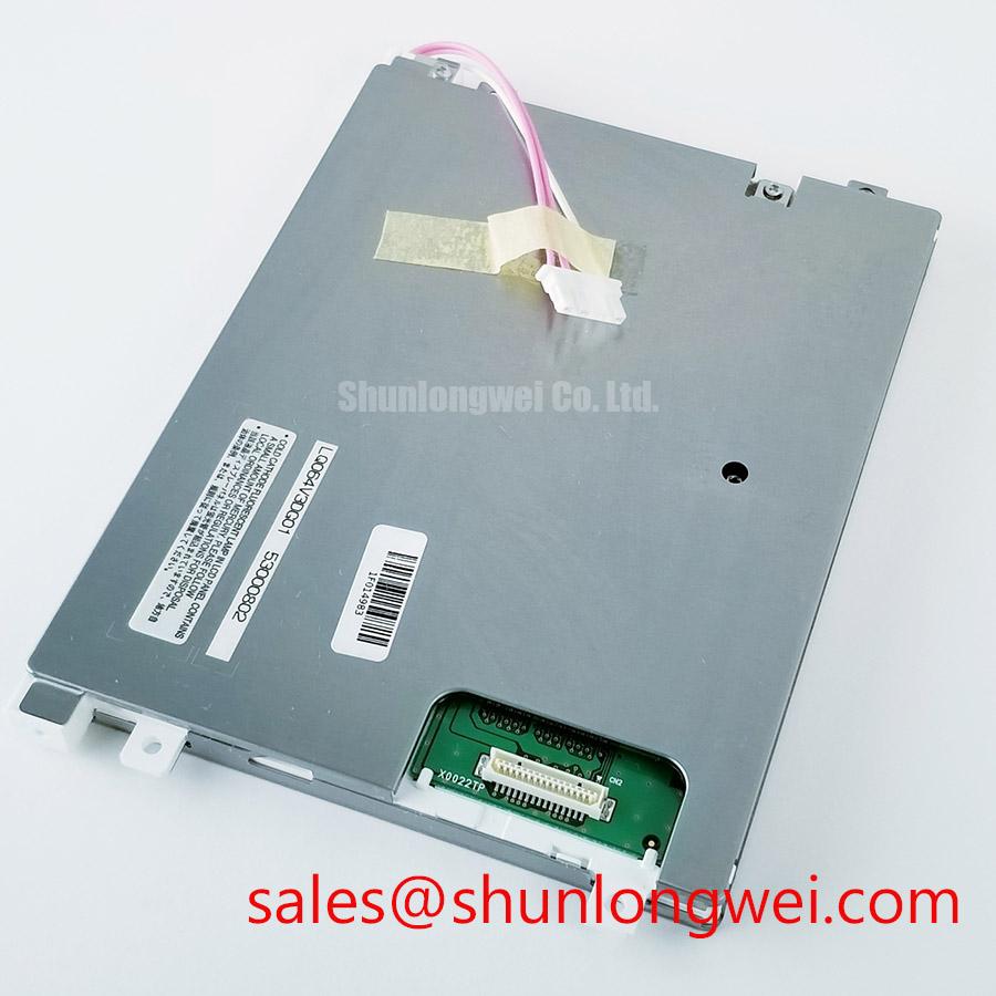
The product identification is Manufacturer: Sharp; Part Number: LQ064V3DG02; Diagonal Size: 6.4 inch; Resolution: 640 x 480; and Interface: TTL / CMOS. This is a TFT-LCD Active Matrix Color Display Module. These baseline specifications establish the display format and electrical interface family, not a complete interchangeability approval.
Preventing Frame Lag & Image Smearing in Cryogenic Storage & Outdoor Industrial Facilities
Compare moving edges and grayscale transitions after the display reaches a stable temperature, keeping the video source and image pattern unchanged. As a Design Consideration, lower temperatures can slow liquid-crystal response and make transitions appear smeared even when the controller continues delivering frames correctly. Separate this optical behavior from repeated frames, interrupted synchronization, and software rendering delays by observing the source signal alongside the displayed pattern.
Extreme-temperature suitability must be established through the specified operating envelope and equipment qualification, rather than inferred from the industrial display category. For this panel, temperature limits, response-time conditions, and environmental test profiles belong in the installation acceptance checklist. A chamber test should remain within the documented limits and distinguish powered operation from storage exposure. Examine the perimeter and mounting points afterward for visible changes without attributing them to a particular sealant chemistry.
Illumination modulation requires a separate check. As an Engineering Recommendation, compare the brightness-control command with measured optical output across the intended adjustment range. Look for unstable illumination, abrupt brightness steps, or interference that appears only at particular settings. Modulation frequency and duty-cycle limits must follow the actual illumination controller and system requirements; they are not established by the panel resolution.
For outdoor evaluation, repeat readability checks with the intended cover window installed. Reflections, enclosure temperature, and operator position can alter usability independently of pixel response. Treat sunlight readability as an assembled-system result rather than an implication of the supplied qualitative luminance description.
Verifying Viewing Angle, Grayscale Stability & Replacement Fit
Display a grayscale ramp and inspect it from the operator’s expected positions before changing image-processing settings. As a Design Consideration, viewing direction can change apparent contrast and tonal ordering. Neither a symmetric viewing cone nor an IPS or MVA operating mode should be assigned to the LQ064V3DG02 without its corresponding manufacturer specification.
Compare the center and edges under both controlled lighting and representative ambient illumination. Surface reflections can obscure dark detail without indicating an electrical fault. Anti-glare and anti-reflection treatments also have different optical effects; evaluate the actual panel surface and any added cover glass instead of treating those terms as interchangeable. The Grayscale Inversion and Why Your Industrial Display Loses discussion provides context for separating angle-dependent appearance from progressive changes during service.
When screening the LQ10D368 alongside this model, treat it as a separate comparison candidate, not an established replacement. The following checks prevent shared branding or a similar product description from becoming an unsupported compatibility claim.
| Selection criterion | LQ064V3DG02 baseline | LQ10D368 comparison requirement |
|---|---|---|
| Manufacturer | Sharp | Confirm manufacturer documentation |
| Diagonal size | 6.4 inch | Consult datasheet and mechanical drawing |
| Resolution | 640 x 480 | Compare native pixel format |
| Interface | TTL / CMOS | Compare electrical interface and pin assignments |
| Installation compatibility | Check drawing, connector, supply, and timing requirements | Evaluate independently before substitution |
For a factory automation machine-tool HMI operator terminal, designers should verify the enclosure aperture, visible area, mounting features, and cable exit against the assembly drawing. Diagonal size alone does not establish those dimensions. If a separate touch overlay is fitted, evaluate glove operation, wet-surface behavior, and coordinate alignment at system level; those are not intrinsic capabilities of the bare LCD.
Constant Luminance Control & Backlight Reliability Verification
Measure luminance at repeatable screen positions while holding the displayed pattern, viewing geometry, and ambient lighting constant. As an Engineering Recommendation, compare cold-start behavior with thermally stabilized operation to distinguish warm-up effects from controller instability or uneven illumination. Record the brightness command and relevant supply behavior alongside the optical observations.
Do not assign an LED architecture or an L70/B50 lifetime rating to this module without supporting manufacturer documentation. Those reliability terms do not establish an operating life by themselves, and they cannot replace the illumination assembly’s actual specification. Service evaluation should instead document observed uniformity, adjustment behavior, and changes under repeatable conditions.
Mechanical integration influences those measurements. As a Design Consideration, keep the frame supported without twisting the module or transferring uneven enclosure pressure into the display stack. Check that gaskets, touch overlays, and cable restraints do not introduce localized loading. Any heat-spreading arrangement should follow measured enclosure temperatures and permitted mounting interfaces, rather than an assumed internal optical material.
The manufacturer’s Sharp Devices Europe Industrial Display Solutions resources provide useful context for industrial display and optical evaluation. Model-specific acceptance still depends on the relevant panel documentation and assembled-equipment tests, particularly where enclosure reflections or thermal conditions affect the measured result.
TTL / CMOS Timing, Pixel Clock & Controller Compatibility
Trace the parallel data and timing signals from the controller to the panel connector before applying LVDS troubleshooting rules. The specified TTL / CMOS interface is not a differential LVDS link. Connector pin counts, differential termination practices, and JEIDA/VESA mapping must not be transferred to this panel by assumption.
As an Engineering Recommendation, compare the controller configuration with the panel’s required data assignments, sampling edge, synchronization signals, and enable behavior. Check signal integrity at the receiving connector, where cable loading and return-path discontinuities affect what the panel receives. Color errors or displaced images can have several causes; compare timing and channel assignments before attributing them to the LCD.
Practical tip: Keep parallel data and clock routing coordinated with a continuous return path, then validate timing at the panel connector with the production cable installed.
Supply voltage, connector pinout, logic thresholds, and power sequencing should come from the model-specific electrical documentation. During integration, compare the measured startup and shutdown waveforms with those requirements, including whether controller outputs remain active while the panel supply is absent. Determine acceptable timing margins from the complete controller, cable, and panel combination.
Finally, investigate interference with the installed enclosure and representative equipment activity. As a Design Consideration, correlate visible disturbances with supply noise and signal timing while changing one condition at a time. Cable routing, grounding, and shielding adjustments require validation in the complete equipment; a functioning panel image does not establish system EMC compliance.