

Content last revised on September 24, 2026
Shielded FFC/FPC Flat Flexible Cable Grounding across 360-Degree Connector Shells
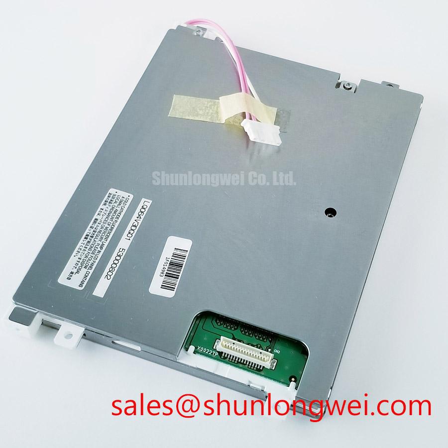
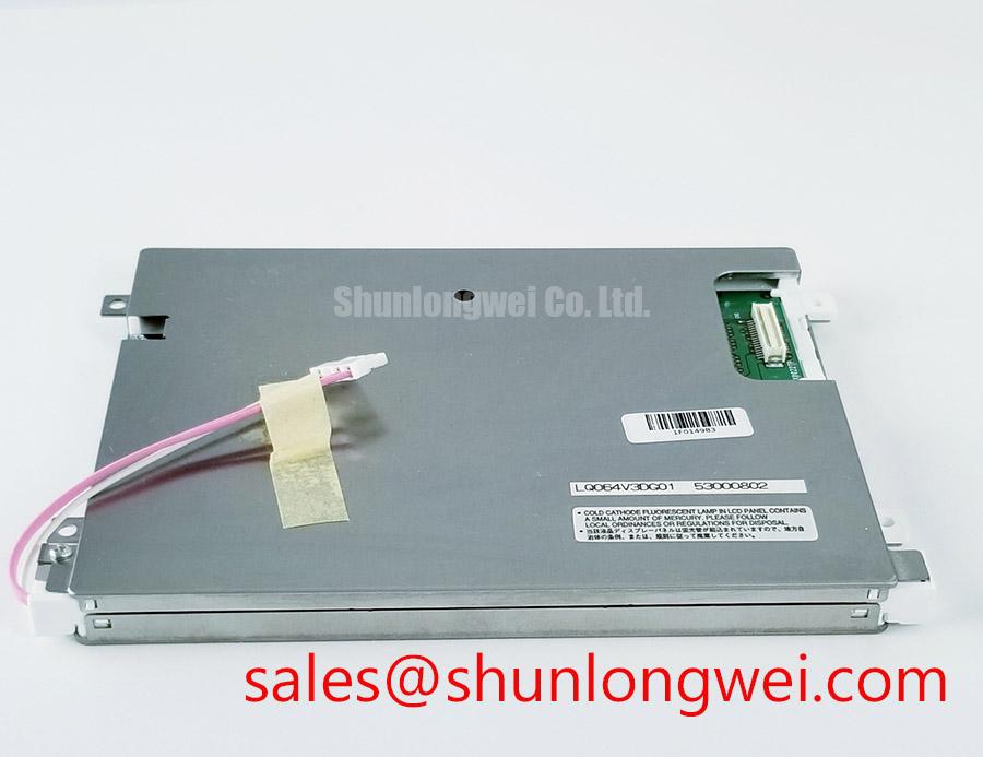
When the LQ064V3DG01 is installed in an industrial HMI, begin at the cable interface rather than replacing the display immediately. Inspect the FFC or FPC for crease marks, uneven insertion depth, contamination, and evidence that the connector locking mechanism has not fully engaged. A cable that appears seated can still produce intermittent image instability if its contact pressure is uneven or if the assembly is exposed to vibration from nearby motors and contactors.
A 360-degree shield termination is an integration feature of the surrounding cable and connector system, not an automatically confirmed attribute of this display module. Where a shielded cable assembly is used, the system designer should evaluate whether the shield is bonded continuously around the connector shell and whether the return path is controlled without creating an unintended circulating-current path. This is a Design Consideration for reducing common-mode coupling. It should be validated with the actual controller, cable, enclosure, and drive system.
Pixel jitter, horizontal noise bands, or a changing display image near a variable-frequency motor drive may involve cable routing, reference potential movement, connector contact quality, or signal-integrity limitations. Do not assign a single cause from the visual symptom alone. Compare the display signal path with a known-good assembly, inspect the cable while the equipment is safely stationary, and use an oscilloscope only where the measurement method is suitable for the interface and ground arrangement.
The module’s official data supplied for this page does not confirm TTL, LVDS, or another specific video interface. Before ordering a replacement, verify the original connector count, contact orientation, signal assignment, cable length, and controller compatibility. The LM64P10 may be reviewed as a separate display model during material planning, but compatibility must be established from the equipment documentation rather than assumed from product category alone.
Sub-zero operation also requires system-level validation. At low ambient temperatures, liquid-crystal response can become slower and visible gray-to-gray transitions may lengthen. This is a Design Consideration, not a published operating-temperature specification for the LQ064V3DG01 in the supplied data. If the enclosure includes a heater strip, designers should verify heater control, warm-up sequencing, condensation management, and display behavior across the actual temperature profile. The resulting limits must be established by the equipment designer through environmental testing.
⚠️ Field Alert: Disconnect power and follow the equipment discharge procedure before inserting or removing an FFC, FPC, or display connector to reduce the risk of contact damage and signal-line disturbance.
Suppressing Acoustic Capacitor Buzz and EMI Emissions across PWM Frequencies
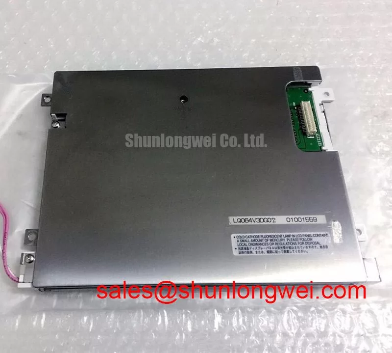
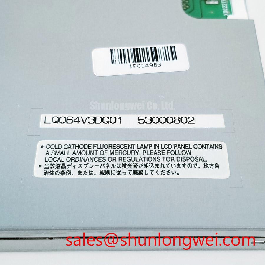
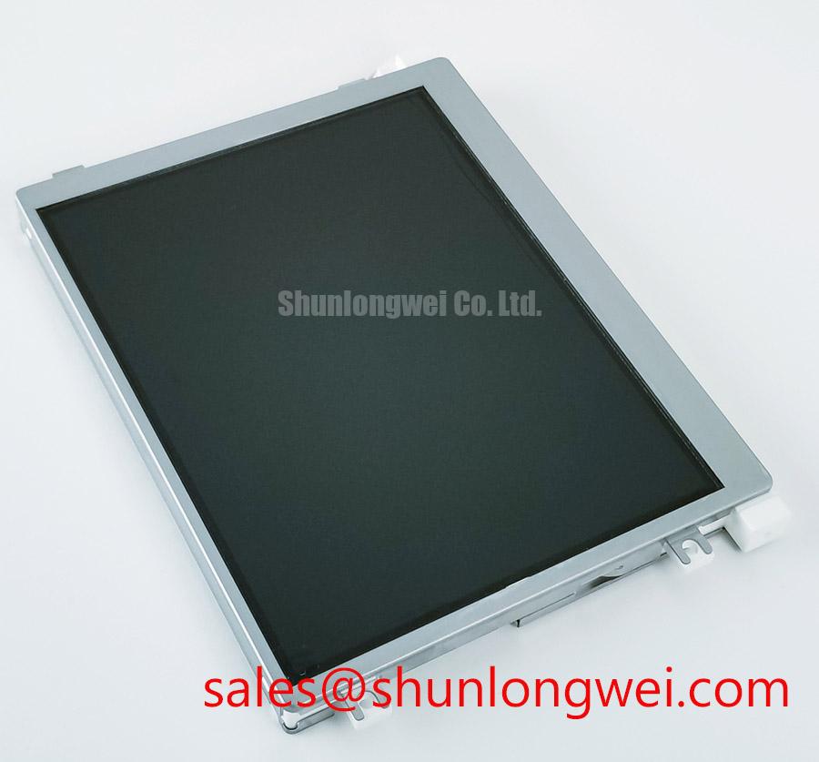
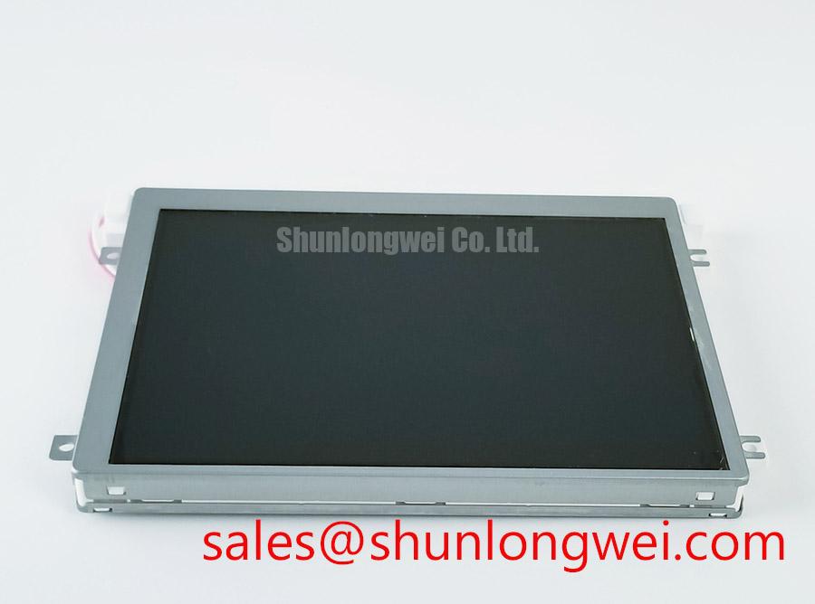
When a repaired operator panel produces a dark screen, excessive flicker, or audible noise, separate the display module from the backlight power path during diagnosis. The LQ064V3DG01 is identified in the supplied data as a TFT-LCD Display Module, but the provided factory information does not confirm whether a particular field assembly uses a CCFL backlight, an LED backlight, a built-in driver, or an external driver. The system integrator should verify the required supply voltage and backlight architecture from the original panel documentation.
For an assembly using a high-voltage CCFL inverter, the ignition waveform, transformer behavior, insulation layout, and lamp condition require dedicated checks. Values sometimes associated with cold ignition are system design parameters and must not be presented as specifications of this Sharp module. Acoustic noise from a capacitor, transformer, or inductor can be influenced by switching frequency, mechanical mounting, load condition, and control-loop behavior. Listening for the noise is useful for locating the area of concern, but it is not sufficient to identify the component responsible.
For an LED-based assembly, the driver should be evaluated for regulated current, enable timing, fault response, and dimming compatibility. A controller’s PWM frequency and duty-cycle behavior can affect visible flicker, camera banding, acoustic response, and perceived brightness. The frequently used range of 200 Hz to 1 kHz is a possible engineering evaluation window for a system designer, not an official rating for the LQ064V3DG01. A claimed 1000:1 dimming ratio or a specific half-life should likewise be supported by the relevant backlight or driver datasheet before it is used in a procurement specification.
Power sequencing deserves the same attention as steady-state voltage. Verify that the controller does not enable the backlight before the display supply and video interface have reached their required states. A white screen, residual image during shutdown, or delayed image may involve sequencing, reset timing, cable contact, controller firmware, or backlight enable behavior. Measure the actual signals against the original system timing rather than applying a generic delay value.
EMI evaluation should include the complete installation: display, cable, controller, DC supply, inverter or LED driver, enclosure, and nearby variable-frequency equipment. The LQ064V3DG01 as a component must not be represented as independently certified for whole-equipment CISPR or EN 55011 compliance. If the display is being considered for a CNC operator panel or robot teach pendant, the finished assembly requires its own conducted and radiated emissions assessment under the applicable equipment requirements.
The LMS700KF01-001 can be reviewed as a separate display product when the equipment architecture requires another display solution. It should not be treated as an automatic electrical substitute for the LQ064V3DG01 without checking connector, controller, backlight, mechanical, and timing compatibility.
Single Vertical Hairline Defect and Sub-Pixel Column Driver Open-Circuit Localization
A single vertical line requires controlled observation before a module is removed from the machine. Display a full red, green, blue, white, and black test image, then record whether the line remains fixed in the same location, changes with image content, or disappears when the signal source is changed. This multi-color bench check is a practical diagnostic method, not a factory acceptance limit for the LQ064V3DG01.
An angled flashlight inspection can help distinguish a visible image defect from a surface reflection, contamination, or localized backlight shadow. Perform the inspection with the panel protected from pressure and with the enclosure opened only according to the equipment service procedure. A line that remains sharply localized may justify checking the signal path and connector seating, while a line associated with pressure, temperature, or mechanical movement requires careful evaluation of the panel assembly. These observations do not establish a single failure mechanism without further testing.
The supplied factory data does not confirm the panel’s transmitter technology, pixel format, clock specification, data hold time, or column-driver construction. Do not infer TTL or LVDS timing margins from the product category. If the controller documentation identifies a digital interface, compare the known-good and suspect paths using an appropriate probe arrangement. Check clock quality, data stability, enable behavior, and reference continuity while avoiding measurement loading that could alter the signal.
When the line follows the display module after the controller and cable have been verified, replacement planning should focus on documented mechanical and electrical compatibility. When the line disappears after a cable change, inspect the removed cable and connector for retention damage rather than assuming that the display itself is defective. If a replacement is installed, confirm the image across the complete operating temperature and brightness range required by the machine.
Optical characteristics also need documentation-based verification. The available official data does not confirm IPS, MVA, TN, viewing angle, contrast, response time, optical bonding, or polarization details for this model. Engineers evaluating a wide-view CNC panel or handheld teach pendant should compare the original panel’s optical behavior in the installed viewing position, including off-axis color shift, glare, cover-window reflections, and brightness uniformity. These are system acceptance conditions unless explicitly stated in the applicable factory datasheet.
Suppressing Localized Thermal Gradients to Prevent Chronic Optical Yellowing
Inspect the rear of the display installation for concentrated heat from the backlight driver, DC converter, processor board, or enclosure power components. A narrow hot area near one edge can produce an uneven visual impression even when the display signal is correct. Before adding a spreader or changing the mounting frame, identify the heat source, confirm clearance, and verify that the proposed mechanical change will not load the panel or obstruct ventilation.
An aluminum heat-spreader rail may be considered where the enclosure design permits controlled heat distribution, but its dimensions, contact method, insulation, and attachment force must be determined by the system engineer. The supplied official data does not specify an allowable rail size, thermal resistance, adhesive type, optical material, or temperature limit for the LQ064V3DG01. Avoid presenting a thermal accessory as an approved Sharp configuration without supporting documentation.
Color shift, localized dimming, or yellow appearance can have several possible contributors, including backlight aging, optical contamination, temperature distribution, driver current behavior, and viewing-angle effects. A controlled comparison should record the display at consistent image content and brightness, then compare the affected area with a known-good panel or reference image. Long-term life claims such as L70, B50, or a 50,000-hour half-life require a source for the specific backlight assembly and operating conditions; they are not confirmed specifications of the display module data supplied here.
Static HMI screens also deserve operating review. If a CNC operator panel or robot teach pendant presents the same status screen for long periods, designers should evaluate screen-saver behavior, controlled image changes, brightness management, and the characteristics of the installed backlight. These measures are application recommendations rather than guarantees against image retention or permanent optical change.
For installations exposed to dust or humidity, inspect the enclosure seal, front cover, cable entry, and condensation control as a complete assembly. Industrial-grade product classification does not by itself establish a finished machine ingress-protection rating. The system integrator should verify environmental requirements, panel mounting, cleaning chemicals, and service access against the equipment specification.
Additional background on TFT-LCD selection, operating principles, and common integration assumptions is available in The Ultimate Guide to Industrial TFT-LCD Technology. For procurement, identify the model as Sharp LQ064V3DG01, request the original equipment interface and mounting information, and validate the complete display assembly before field installation.