Content last revised on October 25, 2026
Initial Inspection and Product Identification
- Disconnect the display assembly from power before checking the panel label, connector orientation, cable retention, and signs of trapped moisture.
- Inspect the bezel gasket for uneven compression, displaced corners, and dust paths without pressing on the active display surface.
- Check mounting clearances and cable strain relief so enclosure tightening does not twist the display frame.
- Record cold-start image behavior, brightness setting, and enclosure temperature before changing controller settings.
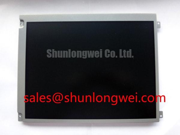
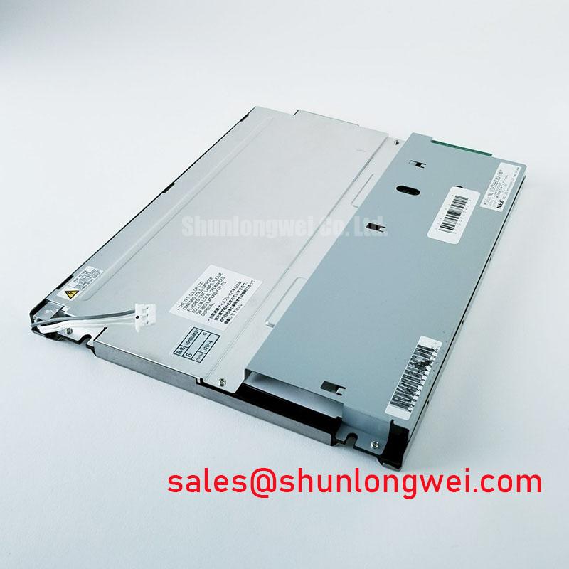
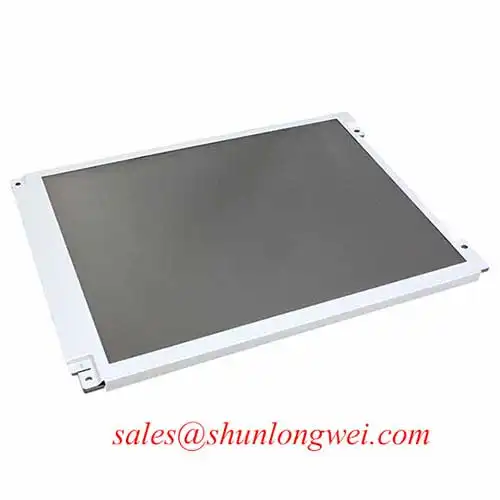
The AUO G121XN01 V001 is an industrial LCD panel with a TFT-LCD active-matrix color display module construction. For replacement assessment, retain the complete model suffix in purchasing records and compare the panel, controller, cable, and mechanical drawing as a connected assembly.
| Product identification | Specification baseline |
|---|---|
| Model | G121XN01 V001 |
| Manufacturer | AUO |
| Product category | Industrial LCD Panel |
| Module construction | TFT-LCD Active Matrix Color Display Module |
| Electrical, optical, mechanical, and environmental limits | Consult Datasheet for the exact revision, including supply, interface, dimensions, response time, temperature limits, and backlight characteristics. |
The integration checks below are Design Considerations, not additional factory ratings. Reliability terminology does not establish this model’s backlight construction, temperature range, or lifetime.
Mitigating Gray-to-Gray (GTG) Response Time Escalation during Cold-Start Machine Power-Up
Compare moving grayscale transitions immediately after startup with the same transitions after the display reaches a stable temperature. Keep the controller timing, brightness command, and test content unchanged so temperature-related smearing can be distinguished from content processing or interface disturbances.
As a Design Consideration, increasing liquid-crystal viscosity at lower temperatures can slow optical transitions. A moving edge that leaves a temporary trail therefore warrants temperature-correlated observation, not an immediate controller replacement. Gray-to-gray behavior also differs from a single black-to-white response measurement; a headline response-time figure does not describe every transition visible in operating graphics.
Perform temperature testing within the panel’s documented operating boundaries. During movement between cold and warm environments, manage condensation before energizing the assembly. Inspect accessible perimeter areas for moisture or mechanical deterioration without assuming a particular sealant chemistry or attributing every image defect to the cell seal.
Cold-start visibility should also be assessed through the installed cover window. Ambient reflections can conceal low-contrast details even when the panel is switching correctly. Record illumination direction and operator position alongside the image rather than treating laboratory contrast as a sunlight-readability guarantee. External heating, where required by a qualified system design, needs separate thermal and mechanical validation.
Contrast Assessment & Liquid Crystal Temperature Behavior
Display a grayscale ramp and inspect it from the intended operator position before adjusting gamma or brightness. Repeat the observation after thermal stabilization and with the bezel fully assembled; this helps separate viewing-angle effects from pressure-related nonuniformity and controller configuration.
As a Design Consideration, liquid-crystal optical behavior and perceived contrast depend on temperature, viewing direction, and the surrounding optical stack. Different LCD technologies exhibit different grayscale and angular behavior, but a symmetric viewing cone or a particular liquid-crystal mode must not be assigned to this model without its specification. The reference on Viewing Angle Characteristics in LCDs explains why off-axis appearance requires its own assessment.
For washed-out midtones, compare the controller’s gamma configuration and documented grayscale reference conditions with a known-good assembly. Do not compensate for an incorrect data configuration by changing timing-controller reference voltages. Such changes can obscure the original fault and compromise the intended grayscale response.
Inspect cover-glass reflections and surface condition separately. Anti-glare and anti-reflection treatments serve different optical functions; neither should be assumed from the industrial product category. The discussion of LCD polarizers and optical construction provides useful context for separating polarization effects from surface reflections.
When comparing the G121XN01 V001 with G121SN01 V402, check resolution, viewing characteristics, mounting geometry, connector assignment, and controller compatibility individually. Similar naming is not evidence of interchangeability.
Luminance Stability & Interpretation of L70/B50 LED Lifetime Metrics
Measure brightness repeatability at a fixed command after thermal stabilization, then inspect uniformity with the enclosure secured in its normal operating configuration. A localized bright patch can involve mechanical loading or optical-stack behavior; it should not automatically be diagnosed as a backlight fault.
As a Design Consideration, distribute mounting loads through the intended attachment points and keep the gasket from bearing unevenly on the display frame. Tightening a bezel to correct a sealing gap can introduce stress rather than improve fit. Assess the enclosure and gasket geometry before changing fastener loading.
Thermal management should preserve the intended heat paths without adding pressure to narrow frame edges. Any supplementary spreader needs evaluation against mounting clearance, electrical isolation requirements, and measured temperatures. Do not assume an internal light-guide material or prescribe an aluminum rail size from the external module description.
Where LED lifetime terminology is used, distinguish lumen maintenance from electrical failure. L70 describes a retained-light-output threshold, while B50 concerns a population percentile under defined evaluation conditions; neither establishes the service life of this panel. A brightness endpoint is also not an MTBF measurement. Maintenance planning should use applicable manufacturer evidence and observed operating conditions, rather than a generic hour claim.
Maintenance Note: Periodically inspect enclosure airflow paths and gasket condition, correcting dust blockage or uneven seating without loading the display surface.
The Industrial Display & HMI Solutions engineering guide provides broader enclosure-integration context without replacing model-specific limits.
Logic Supply Voltage Sequencing to Reduce Driver IC Latch-Up Risks
Match the panel connector assignment to the controller schematic before applying power, then capture the actual supply, enable, and video transitions at the receiving assembly. The system integrator should verify the required supply voltage from the original panel documentation.
As a Design Consideration, avoid driving signal pins while the receiving circuitry is unpowered unless that condition is expressly permitted. Compare startup, shutdown, and interrupted-power behavior with the specified sequence. Sequencing assessment can reduce integration risk, but it does not establish unconditional immunity to latch-up.
Identify the actual interface before applying transmission-line rules. For a documented differential interface, assess pair routing, connector transitions, termination, and clock quality against its electrical requirements. TTL signaling is not differential, and JEIDA/VESA mapping checks apply only where the specified interface uses those conventions.
Split images, incorrect colors, or intermittent pixels warrant comparison of mapping, timing, cable continuity, and receiver waveforms. If disturbances correlate with nearby servo operation, examine cable routing, shield termination, and grounding as system-level EMC considerations—not as evidence of a single predetermined panel defect.
The G121ACE-LH1 is another display option for controller and power-architecture comparison, not an assumed backlight-driver accessory. For railway passenger-information or cab-signalling display assessment, qualification belongs to the complete equipment assembly; panel selection alone establishes neither railway suitability nor compliance.