Content last revised on October 14, 2026
AA121XK04 Display Inspection and Replacement Assessment
- Disconnect equipment power, verify discharge, and inspect the AA121XK04 display connector for incomplete seating, damaged contacts, or cable tension.
- Record whether the screen is completely dark, faintly displaying an image, or showing unstable pixels before disturbing the harness.
- Compare the panel identification, mounting points, and connector orientation with the removed assembly and the equipment service drawing.
- Inspect the bezel clearance and cable routing for pressure against the display face or movement at the connector latch.
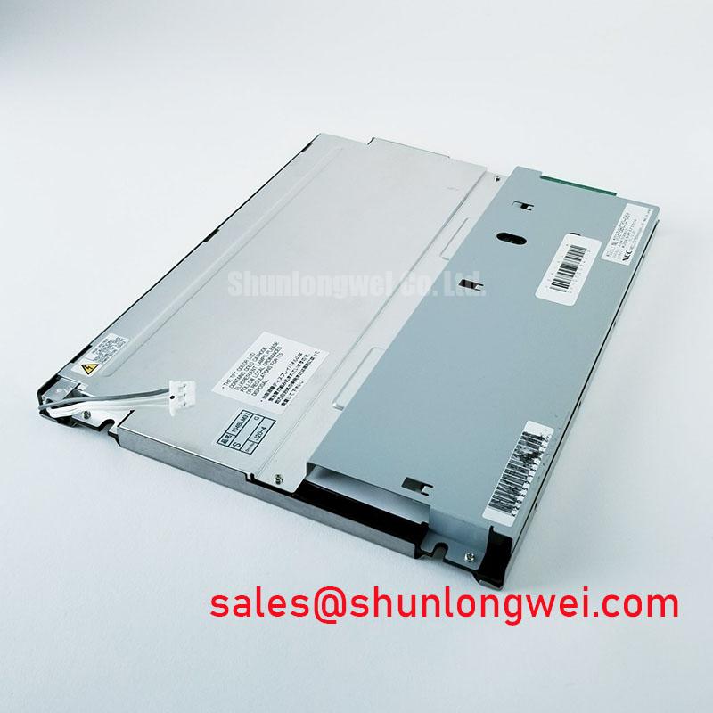
The AA121XK04 is a Mitsubishi Electric TFT-LCD active-matrix color display module in the industrial LCD/HMI panel category. Replacement assessment should separate the panel itself from the host controller, display harness, and backlight power circuit. A dark screen alone does not establish which assembly requires replacement.
| Product identity | Specification baseline |
|---|---|
| Model | AA121XK04 |
| Manufacturer | Mitsubishi Electric |
| Product category | Industrial Grade LCD/HMI Panel |
| Module construction | TFT-LCD Active Matrix Color Display Module |
| Electrical, optical, and mechanical acceptance values | Consult Datasheet: resolution, dimensions, interface, supply ratings, backlight configuration, timing, and temperature limits. |
Backlight Driving, Dimming & Flicker Troubleshooting
Separate image generation from illumination by inspecting a dark screen under controlled external light while the host displays a known test pattern. A visible but dim image directs attention toward the illumination chain, although power sequencing and controller faults still require exclusion. Record backlight enable, brightness command, and driver behavior together rather than judging the panel from brightness alone.
Design Consideration: WLED constant-current operation and PWM dimming are integration topics, not established AA121XK04 specifications. For an LED-based illumination circuit identified in the equipment documentation, compare the driver current waveform with its enable and dimming inputs. At reduced brightness, unstable pulse delivery can produce visible modulation even when the average command appears steady. Select operating conditions through driver limits and complete-display testing, not a universal frequency prescription.
A lamp-based driver requires its own documented ignition and operating checks; LED-driver measurements cannot be transferred to that circuit. Keep illumination tests separate from image-interface timing. Clock jitter, setup time, and hold time belong to the transmitter and receiver timing budget and should be checked at the receiving connector under the intended operating conditions.
For display-chain comparisons, NL6448BC20-08E is a separate display product, not an AA121XK04 backlight-driver accessory. The Tianma NLT industrial display portfolio provides broader display-technology context without establishing compatibility between these modules. Backlight brightness decay and mean time between failures describe different outcomes; neither supports an AA121XK04 lifetime guarantee without applicable manufacturer test conditions.
Industrial EMI Noise Immunity, Chassis Shielding Continuity & Common-Mode Ferrite Chokes
Correlate pixel instability or horizontal bands with equipment switching events before modifying the display harness. Capture the disturbance alongside panel power and the relevant interface signals. A repeatable relationship with motor operation can guide investigation toward conducted or coupled interference, but connector intermittency and supply disturbances can produce similar symptoms.
Design Consideration: Check existing shield termination and chassis bonding against the equipment drawing. Where a shielded cable is specified, preserve its intended termination geometry and avoid leaving a long exposed section beside switching conductors. Do not add chassis connections indiscriminately: an altered return path can change common-mode current through the assembly.
A common-mode choke is a system-level option, not an assumed panel feature. Evaluate suppression components only after identifying the coupling path, then check image integrity and interface waveforms with the component installed. Ferrite selection depends on the disturbance spectrum, cable construction, and signal requirements; adding a ferrite does not establish EMC compliance.
When interference changes with brightness, inspect the backlight switching waveform and its supply return alongside the image link. For broader harness and enclosure assessment, Industrial Display & HMI Solutions offers supporting integration context. Keep the AA121XK04 repair decision tied to measurements at its actual connections.
Display Interface Synchronization & Logic Power Rail Verification
Match connector assignments to the host schematic before applying power or connecting a substitute display. Do not assume a TTL 24-bit RGB interface for the AA121XK04. Establish signal direction, ground returns, supply connections, and control functions from the panel-specific connection drawing rather than connector appearance.
Engineering Recommendation: Capture the logic supply rise, interface activity, and display-enable transition in one acquisition. Compare their order and timing with the documented sequence. Check voltage at the panel connector under load, since a stable controller-board rail can conceal a harness voltage drop or intermittent contact.
For a documented parallel RGB link, examine clock-to-data timing and synchronization polarity at the receiver. For a documented differential link, examine pair integrity and the controller’s required data mapping instead. These are distinct troubleshooting paths: JEIDA/VESA mapping and differential routing rules must not be applied to a parallel bus simply because the fault resembles a split image.
Field Alert: Disconnect equipment power and verify discharge before reseating the display or backlight connector. During replacement evaluation, treat AA104VC02 as a separate comparison candidate, not a drop-in equivalent. Compare geometry, mounting, resolution, pin assignments, interface timing, and illumination requirements independently. Matching a manufacturer name or connector shape is insufficient evidence of interchangeability.
Mitigating Gray-to-Gray (GTG) Response Time Escalation during Cold-Start Machine Power-Up
Compare moving edges and gray transitions immediately after startup with the same pattern after thermal stabilization. Slower liquid-crystal response at lower temperature can contribute to trailing images, while supply instability or incorrect timing can cause different startup artifacts. Keep the test pattern, brightness command, and controller configuration unchanged so the comparison remains meaningful.
Design Consideration: Distinguish gray-to-gray response from the optical response metric used in the panel specification. Controller compensation should be evaluated only where the controller supports it and the panel operating conditions permit it. Do not introduce heating or overdrive as an assumed AA121XK04 requirement.
For potential AGV or forklift telematics integration, designers should assess temperature exposure, vibration restraint, sunlight readability, and enclosure sealing at assembly level. Panel contrast measured under controlled conditions does not establish readability through a vehicle cover lens. The Winstar TFT-LCD product resources provide general optical-selection context, not AA121XK04 sunlight-performance certification.
Inspect mounting clearance and harness slack through the equipment’s approved thermal and vibration tests. Avoid bezel pressure, repeated flexing at the connector exit, and unsupported cable movement; do not assign a bend-life figure without cable-specific evidence. If a static interface leaves a residual pattern, compare it with a changing test image after normal operation resumes. Record persistence and temperature before attributing the symptom to permanent panel damage.