Content last revised on October 15, 2026
Thermal Expansion Clearance Sizing across Heavy Industrial Metal Enclosure Cutouts
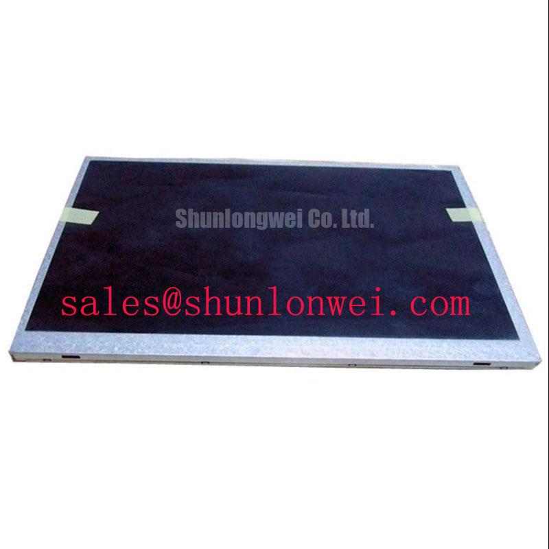
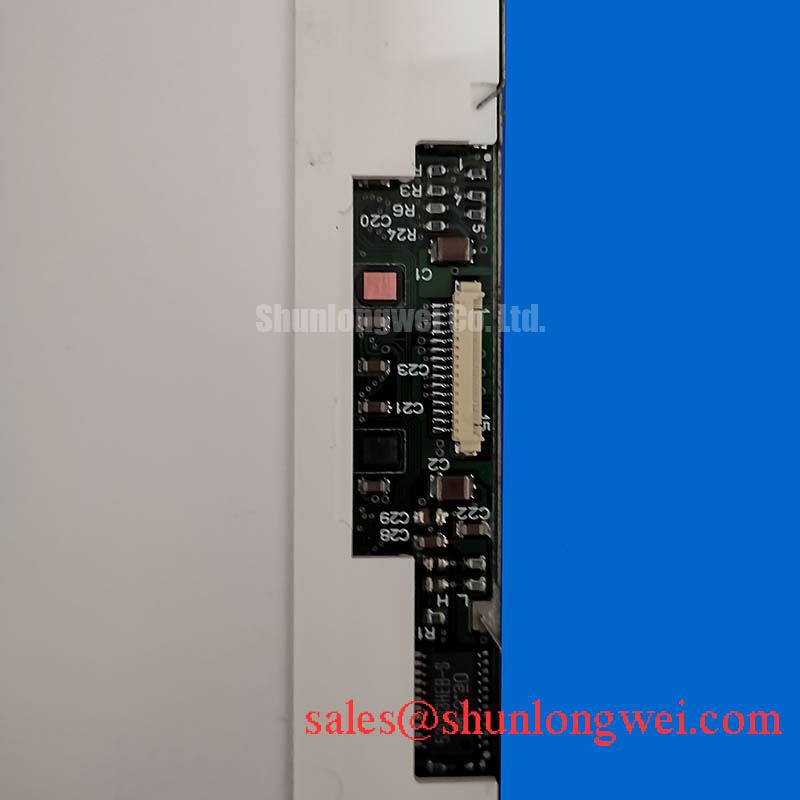
Start the mechanical evaluation by placing the removed display and the G121ACE-LH2 against the enclosure drawing, with attention to the visible aperture, bezel contact area, mounting-hole pattern, connector clearance, and cable bend path. The available product classification confirms an industrial-grade TFT-LCD active matrix color display module, but it does not establish a universal chassis cutout dimension or mounting-hole tolerance. Those dimensions belong to the panel drawing and the host equipment assembly.
Metal bezels and panel frames do not expand in exactly the same way during repeated temperature changes. A rigid cutout can transmit stress into the display assembly when the aperture is undersized, when fasteners pull the frame unevenly, or when a gasket is compressed outside its intended contact area. During service, inspect the panel with the fasteners released and then under normal enclosure tension. A change in localized brightness, corner shading, or dark-field uniformity after tightening can point to mechanical loading or optical stack distortion rather than a controller fault.
Use a cross-pattern installation sequence so the frame seats evenly. Any torque value selected for suitable M3 hardware during this integration discussion is a general design consideration, not an AUO factory specification for the G121ACE-LH2. The actual limit should follow the panel drawing, the fastener material, the thread engagement, and the enclosure assembly procedure. Avoid allowing a screw head, washer edge, or stiff gasket section to press directly on an unsupported display region.
For equipment such as a railway passenger information terminal or cab signalling display, evaluate the complete bezel assembly rather than the LCD module alone. Door flex, vibration, cable restraint, and repeated service access can change the mechanical load path. A thermal chamber or controlled warm-up inspection can help identify whether a display artifact follows enclosure temperature or connector movement. Record the image condition at cold start, stabilized operation, and after power removal so the replacement decision is based on repeatable observations.
Backlight service life must also be treated as a system question. A claimed LED operating-life curve, brightness-retention point, or MTBF value cannot be assigned to this AUO model from its product category alone. The repair engineer should obtain the applicable panel or backlight documentation and evaluate the constant-current driver, thermal path, operating brightness, and ambient enclosure temperature together.
Diffuser Film & Prism Sheet Thermal Buckling Prevention under Continuous Full-Duty Operation
Continuous full-duty operation makes the heat path around the display edge important. Keep the rear assembly, bezel, and any metal carrier free from local pressure points that could transfer heat or mechanical stress into the optical area. Do not add an aluminum rail, adhesive pad, thermal interface layer, or spacer unless its thickness, contact pressure, electrical isolation, and effect on the original assembly have been checked against the panel construction.
Visible bands, uneven luminance, or a patch that changes after warm-up should be examined from several viewing angles and brightness settings. A stable defect that follows the panel may indicate optical or mechanical damage, while a defect that follows the video source may indicate signal integrity, timing, or controller behavior. This distinction is useful when evaluating the G121ACE-LH2 against a removed unit because it separates panel replacement questions from host-system faults.
The G121ACE-LH2 should be integrated using the original panel support strategy wherever practical. Preserve the intended edge supports, avoid clamping across unsupported areas, and route the display cable so it does not pull the panel toward one corner. Where the enclosure uses a narrow metal carrier, check whether the carrier touches the panel frame continuously or only at defined mounting points. Uncontrolled contact can create a local thermal path while also changing the frame load during expansion.
For high-brightness operation, measure the temperature distribution around the display assembly rather than assuming that the driver board temperature represents the panel temperature. A thermal camera can reveal a concentrated hot area near the backlight input, while a surface probe can help confirm the trend during a controlled test. The result should be compared with the original panel and the applicable AUO documentation before any heat spreader modification is accepted.
| Evaluation item | G121ACE-LH2 | Related replacement assessment |
|---|---|---|
| Manufacturer | AUO | Confirm manufacturer and revision on the removed panel |
| Product category | Industrial grade LCD/HMI panel | Compare the complete mechanical and electrical interface |
| Display construction | TFT-LCD active matrix color display module | Do not infer backlight or connector details from category alone |
| Form factor status | Decoded baseline / standard form factor | Match the enclosure drawing and service assembly |
| Cross-reference | Use the original panel documentation | Review G121SN01 V2 as a separate same-size or same-resolution evaluation candidate only after interface comparison |
The comparison above is an engineering screening aid, not a claim that the related panel is a drop-in substitute. Connector position, active area, mounting pattern, optical stack, controller timing, and backlight control must agree before a cross-reference is accepted.
Suppressing Acoustic Capacitor Buzz & EMI Emissions across 200 Hz to 1 kHz PWM Frequencies
Backlight troubleshooting should begin by identifying whether the installed assembly uses the same drive method as the original panel. Do not assume CCFL ignition hardware, LED constant-current operation, or a particular dimming input from the G121ACE-LH2 product category. The system integrator should verify the required supply voltage, backlight type, enable logic, dimming method, and protection behavior from the original panel documentation.
When a service display produces audible noise during brightness adjustment, observe the driver, wiring, and enclosure together. A pulse-width control signal can interact with inductors, capacitors, transformer structures, cable resonance, or mechanical mounting. Audible sound that changes with duty cycle should be correlated with the driver waveform and the panel brightness response rather than assigned to the LCD glass without measurement.
The stated 200 Hz to 1 kHz PWM range is a system-level evaluation range for dimming behavior, not an official G121ACE-LH2 rating. Engineers should verify whether the selected driver accepts that control range and whether the resulting duty-cycle response is sufficiently linear for the equipment display. Check low-brightness behavior, startup response, visible flicker, and recovery after a protection event. A separate constant-current driver reference such as NL6448BC33-24 may help with topology comparison, but it does not establish compatibility with this AUO module.
Older equipment may contain high-voltage cold-cathode circuitry, while a replacement assembly may use a different backlight architecture. Mixing the original inverter assumptions with a different panel can create overvoltage, incorrect enable sequencing, or an unrecognized fault output. Keep the replacement evaluation at the interface level: identify the driver output, confirm the panel-side connector assignment, verify the control polarity, and monitor the panel during startup and dimming transitions.
Industrial EMI Noise Immunity, Chassis Shielding Continuity & Common-Mode Ferrite Chokes
Route the display cable as a controlled signal path from the host controller to the panel connector, keeping it away from high-current motor, inverter, relay, and switching power wiring where the enclosure permits. Pixel jitter, horizontal noise bands, or intermittent image loss near a variable-frequency drive can result from several interacting conditions, including return-path discontinuity, connector contact quality, timing margin, cable placement, and common-mode coupling.
For an LVDS or other differential interface, verify the actual signaling standard, lane order, clock relationship, data format, and connector pinout from the host and panel documentation. The G121ACE-LH2 listing does not by itself establish an LVDS pin assignment, JEIDA or VESA mapping, cable impedance, or power-sequencing requirement. When the signal format is confirmed, inspect the cable termination and shield continuity at both ends according to the equipment’s grounding architecture.
A common-mode ferrite or shield termination can alter conducted noise behavior, but its impedance profile, placement, current rating, and grounding arrangement must be selected from measured interference and the complete system topology. It should not be added as a universal cure. Use an oscilloscope at the receiving interface and compare the suspected display path with a known-good path while the motor drive operates through the same load cycle.
💡 Pro Tip: Keep differential-pair routing physically balanced and maintain a continuous return path so pixel-clock timing remains stable during switching events.
For a railway passenger information system or cab signalling display, inspect the enclosure bonding points, cable clamp pressure, connector backshell, and service-panel seams as part of the same EMC review. The display module itself cannot independently claim compliance with whole-equipment emissions or immunity standards. A broader maintenance reference is available in Industrial Display & HMI Solutions.
Optical behavior also matters when assessing apparent EMI faults. LCD polarizers and optical glass influence how reflections, glare, and contrast changes are perceived; the general operating principles are described in Liquid-Crystal Display polarizer and optical glass references. The thin-film transistor context can be reviewed through amorphous silicon TFT technology references. These references provide industry background, not model-specific AUO specifications.