Content last revised on November 1, 2026
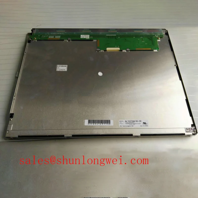
NEC NL10276BC20-08 LCD Replacement Assessment
Check the panel label and disconnected display harness before powering a replacement, then inspect the bezel supports for uneven gasket compression or trapped cable insulation. The NEC NL10276BC20-08 is a 10.4-inch LCD display with 1024 × 768 XGA resolution and a single-channel, 6/8-bit LVDS interface (Official Specification). Matching the connector outline alone does not establish electrical compatibility.
Its specified optical values are 400 cd/m² typical luminance and a 900:1 contrast ratio, with a stated temperature range of −30°C to +80°C (Official Specification). These parameters provide a useful starting point for replacement assessment, but enclosure reflections, controller configuration, and mechanical fit still determine the installed result. At the compatibility review, consult the panel documentation for supply voltage, connector assignments, power sequencing, mounting dimensions, and backlight requirements.
Controlled 100-Ohm Differential Impedance Routing for LVDS Signal Integrity
Trace each LVDS pair from the controller connector to the panel harness, checking pair continuity, polarity, shield termination, and any adapter-board transitions. As a Design Consideration, conventional LVDS interconnects use a nominal 100 Ω differential impedance; this is an interconnect design reference, not a measured specification for the supplied cable. Preserve pair geometry through connectors and bends, and evaluate discontinuities against the actual transmitter, receiver, and harness arrangement.
A split image, unstable colors, or intermittent pixel noise warrants a comparison of controller timing and data mapping before condemning the panel. The specified 6/8-bit interface capability does not establish the host’s selected color depth or mapping convention. Engineers should reconcile the controller configuration with the panel pin assignment, including JEIDA/VESA mapping where applicable. Supply ramp and signal-enable timing should follow the documented sequence rather than a generic timing prescription.
For interference that appears only during nearby drive operation, compare the display with the disturbance source active and inactive while monitoring supply integrity and signal behavior. As a Design Consideration, cable separation, return-path continuity, and enclosure bonding can influence susceptibility. An LVDS interface does not independently establish equipment-level EMC compliance.
The NL6448BC20-35D offers another NEC model for a documented replacement comparison, not an assumed interchangeable unit. Compare resolution, active area, mounting geometry, and electrical assignments individually. Likewise, the NL6448BC33-53 comparison provides related display context without establishing common backlight-drive requirements.
Full-Screen Primary Color Screening for Sub-Pixel Defects and Background Uniformity
Display uniform red, green, and blue fields, followed by neutral gray, white, and black backgrounds, using a stable native-resolution source. Record persistent bright or dark locations separately from broad brightness gradients. As an Engineering Recommendation, retain the same image settings and viewing position when comparing the removed panel with the replacement; automatic brightness changes can otherwise obscure the result.
A faint image visible under oblique external illumination can help distinguish image generation from an illumination problem, but it does not identify the failed part by itself. Continue by checking the backlight supply path, enable command, connectors, and any documented driver-status output. Open-load or short-circuit protection belongs to the relevant driver specification; its presence and thresholds should not be inferred from the LCD model number.
Line defects also require a broader check than visual inspection alone. Compare their position across test patterns and examine whether harness movement changes the symptom without pressing on the glass. A persistent line does not, by itself, prove an internal bond fracture. Supply instability, signal corruption, controller faults, and panel faults can produce overlapping symptoms.
For background uniformity, compare the panel before final bezel closure and after assembly. As a Design Consideration, uneven support or excessive gasket compression can contribute to pressure-related optical nonuniformity. Seat the module without twisting its frame, keep gasket joints clear of active viewing areas, and follow the specified mounting method rather than tightening until visible leakage disappears.
Viewing-Angle and Ambient-Light Assessment for Multi-Angle Consoles
Inspect grayscale steps and fine text from the operator’s expected viewing positions, including standing and seated positions where relevant. The supplied specifications do not establish an IPS/MVA architecture or a symmetric viewing-angle rating, so acceptance should rest on the documented optical limits and the installed viewing assessment. Look for changes in dark-detail visibility, color balance, and apparent contrast rather than brightness alone.
The 400 cd/m² typical luminance describes emitted display brightness; it does not guarantee sunlight readability. As a Design Consideration, reflected ambient light raises the apparent black level and can reduce usable contrast. The distinction between luminance and other optical quantities is explained in Photometry (Optics). Assess the assembled cover window and panel together because reflections from either surface affect readability.
Do not assume an anti-glare or anti-reflection treatment from the nominal contrast ratio. Check surface-treatment documentation before specifying cleaning materials or adding an optical overlay. For a high-voltage substation protection or SCADA dispatch console, engineers should evaluate alarm colors, schematic labels, and operator sightlines in the intended enclosure. Any touch overlay requires its own controller compatibility and glove or moisture-response assessment; those capabilities are not established by the LCD specifications.
−30°C to +80°C Temperature Range and Low-Temperature Display Response
Assess cold-start image transitions separately from steady-state image quality across the specified −30°C to +80°C temperature range. As a Design Consideration, liquid-crystal response can slow as temperature falls, making changing text or moving indicators appear less distinct. A temperature-range rating does not establish a particular gray-to-gray response time at every temperature, nor does it remove the need for enclosure thermal assessment.
During environmental evaluation, monitor the display location rather than relying only on room temperature. Internal power dissipation and restricted airflow can create a different thermal condition behind the panel. After a cold assembly enters warmer humid air, allow condensation to clear before energizing it. Inspect external sealing and cable-entry arrangements without attributing an undocumented sealing material or ingress rating to the module.
Maintenance Note: Periodically inspect ventilation paths and bezel gaskets, correcting blockage or displaced seals without adding pressure to the display frame.
For ongoing inspection planning, Industrial Display & HMI Solutions provides broader integration context, while NEC provides manufacturer background. Track brightness under repeatable settings and investigate changes alongside driver operation, contamination, and temperature; brightness depreciation and failure rate are different measures and should not be treated as interchangeable lifetime claims.