


Content last revised on October 9, 2026
Field Replacement and Environmental Evaluation of the Planar EL320-256-FD6
| Model | EL320-256-FD6 |
| Manufacturer | Planar |
| Product Category | Industrial Electroluminescent Display/HMI Panel |
| Panel Technology | Electroluminescent panel |
| Specification Status | Decoded baseline / standard form factor |
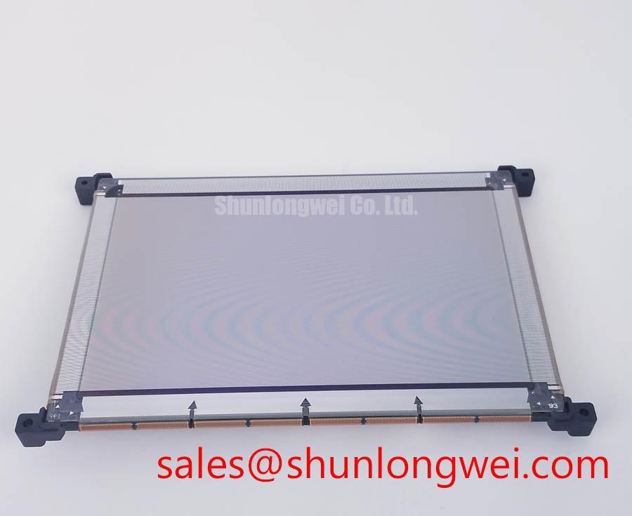
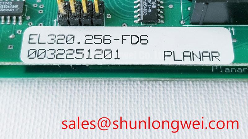
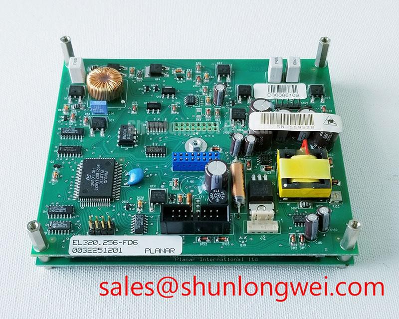
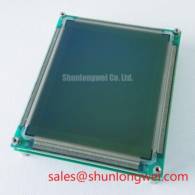
Begin a field replacement by isolating the display from the control cabinet, recording the original cable orientation, and comparing the replacement panel’s mechanical envelope with the existing mounting frame. The EL320-256-FD6 is identified as a Planar electroluminescent industrial panel intended for equipment where clear visual feedback is required from a dedicated HMI or monitoring interface.
An electroluminescent panel does not behave like a conventional liquid crystal assembly. Its light-emitting layer is driven by an electrical excitation system rather than by a separate liquid crystal shutter and conventional backlight arrangement. This distinction matters during troubleshooting. A dark screen should be investigated through the complete display chain, including the host controller, panel interface, excitation circuitry, grounding, cable seating, and power sequencing. It should not be diagnosed from appearance alone.
For a high-voltage substation protection or SCADA dispatch console, technicians should first preserve the original wiring reference before disconnecting the failed unit. Mark the cable position, inspect the connector latch, and check for pin displacement or uneven insertion. The replacement panel should be evaluated against the original system documentation for interface compatibility, mechanical clearance, display timing, and required drive conditions.
Low-temperature operation requires a controlled comparison between the panel, the enclosure, and the display electronics. Do not treat a general electroluminescent construction as automatic proof of operation at a specific low temperature. If the equipment specification calls for operation at −40°C, the complete installed assembly should be tested at that condition, including the host electronics, cable insulation, connector retention, sealing materials, and panel drive electronics. The panel alone cannot establish the environmental rating of the finished console.
Mechanical shock evaluation should focus on how the panel is supported inside the cabinet. A rigid bezel can transfer impact into the glass or connector area, while excessive clamp pressure can create localized stress during thermal cycling. Use the original mounting architecture where possible, maintain even support around the panel perimeter, and prevent cable weight from loading the connector. Any requirement involving high shock levels, including a proposed 100G test condition, must be defined by the equipment qualification plan and verified with the installed assembly rather than assumed from the product category.
Viewing performance also needs to be checked at the actual operator position. The stated product information identifies the device as an electroluminescent panel, but it does not establish a confirmed viewing-angle figure for this specific model. When the display is used in a dispatch console, inspect the screen from normal seated and standing positions, then compare contrast and legibility under cabinet lighting, emergency lighting, and reduced ambient illumination.
Panel replacement is also an opportunity to examine long-term HMI behavior. Static alarm banners, breaker status fields, and fixed navigation elements should be rotated or managed according to the host application’s display policy where practical. Persistent image retention, uneven illumination, or local darkening can involve the panel, drive waveform, thermal environment, or operating history. The correct maintenance action is to compare the affected area with a known-good screen pattern and review the electrical conditions at the panel interface.
For broader enclosure, sealing, and installation planning, engineers can consult the Industrial Display & HMI Solutions reference. It provides a useful framework for assessing industrial display integration in environments where dust, humidity, vibration, and temperature variation influence the complete assembly.
⚠️ Field Alert: Disconnect cabinet power and wait for the system discharge procedure to complete before inserting or removing the panel cable.
Drive-System Compatibility and Waveform Evaluation
When the EL320-256-FD6 is connected to an existing drive system, the first engineering task is to confirm that the host electronics and panel interface belong to the same electrical architecture. An electroluminescent panel may require a dedicated alternating excitation waveform, but the available product identity alone should not be used to assign a drive voltage, pulse amplitude, row and column timing, or charge-recovery topology.
For a repair engineer, the practical measurement point is the complete signal path. Compare the replacement assembly with the original panel while observing the host controller output, enable sequence, drive activity, and return path. A missing display can result from absent panel excitation, incorrect sequencing, an open interconnect, a disabled controller output, or a protection response elsewhere in the system. These conditions require waveform comparison against the equipment’s approved reference, not a single voltage check at the connector.
High-voltage alternating drive systems are sensitive to insulation condition, connector contamination, cable routing, and parasitic coupling. Keep the panel cable away from switching nodes and maintain the original routing where possible. The system designer should minimize unnecessary loop area and verify that switching transients remain within the limits of the controller, cable insulation, connector system, and panel interface. Any proposed pulse range such as 180 to 240 V peak must be treated as a system-specific engineering value unless it is confirmed in the original panel documentation.
Charge-recovery circuitry can reduce the energy required to reverse the electric field in an electroluminescent load, but its operation depends on the actual panel capacitance, switching devices, resonant components, timing, and protection network. A service replacement should therefore be assessed with the original drive board, not connected to an improvised high-voltage source. During bench evaluation, use an appropriately rated probe and compare the positive and negative portions of the waveform for symmetry, overshoot, ringing, and unwanted DC offset.
Unbalanced excitation can create uneven brightness or localized stress over time, while excessive transient energy may affect the dielectric system or switching components. The appropriate acceptance limits are determined by the original drive design and equipment qualification requirements. Engineers should record the display condition during startup, steady operation, dimming or intensity changes, and shutdown. Residual illumination after power removal should be evaluated together with the discharge path and controller timing rather than attributed to the panel without evidence.
Temperature testing should include a gradual transition between ambient and the specified operating range. Observe connector retention, cable flexibility, panel appearance, drive stability, and recovery after the temperature cycle. The electroluminescent construction may respond differently from a liquid crystal panel, but that general principle does not replace model-specific environmental qualification. When the panel is used in a substation protection or SCADA console, the final test should include the actual alarm graphics, status indications, fixed text, and operator viewing geometry.
Display content and interface terminology also need careful handling. A system that presents status indications or graphical elements should be checked against the host software and display requirements. The sRGB standard color space can provide a reference for systems that generate color-managed content, but it does not by itself confirm the color performance of this electroluminescent model. Likewise, a controller using a packetized video architecture should be verified against its actual interface documentation; the DisplayPort High Bit Rate packetized protocol is not evidence that this panel natively accepts DisplayPort input.
For a mechanically different or electrically distinct replacement assessment, engineers may review EL640.480-AA1 as a separate industrial display reference. It should be compared through documented resolution, connector arrangement, drive requirements, mounting dimensions, and host compatibility rather than selected solely because both products are associated with industrial display equipment.