


Content last revised on September 22, 2026
Thermal Cycling Degradation of Polarizer Adhesives and Sealant Gasket Integrity
Inspect the perimeter of the display before placing it into an enclosure. Look for lifting edges, contamination on the sealing land, compression marks in an existing gasket, and frame distortion that could transfer local stress into the glass. These checks are useful for a cab display or passenger information terminal exposed to repeated temperature changes, but the supplied factory data does not establish a qualified operating range for this specific model. Do not assign a range such as minus 30 to plus 85 degrees Celsius to NL4864HC13-01A without the applicable NEC documentation.
Temperature cycling can alter the mechanical relationship between the glass, polarizer, frame, adhesive layers, and enclosure. In a service evaluation, record the display condition while cold, during warm-up, and after the assembly returns to a stable ambient condition. Observe whether image uniformity, startup timing, grey transitions, or edge appearance changes with temperature. These observations are diagnostic evidence, not proof of a particular adhesive or sealant failure.
Grey-to-grey response behavior should be checked through the complete display chain. A slow transition can involve the panel, the timing controller, grey-scale voltage generation, gamma correction, image source timing, or temperature-dependent system behavior. The T-CON operating sequence and gamma reference levels should therefore be compared with the known-good assembly. The required supply voltage, enable sequence, reset timing, and signal format remain system-level items that must be verified from the original panel documentation.
Mechanical installation deserves the same attention as thermal testing. The frame should sit evenly against the gasket, with no point loading from a distorted bezel or uneven fastener tightening. A sealing interface that is too loose may admit dust or moisture, while excessive compression can create local optical non-uniformity. This is a Maintenance Note: inspect the enclosure gasket and ventilation path during scheduled service, and disconnect power before removing the display cable.
Surface Anti-Glare and Anti-Reflective Treatment for High Ambient Readability
Readability testing should begin with the complete installed assembly rather than the bare panel. Position the display at its actual operator viewing location, check reflections from cab glazing and instrument covers, and compare the screen with the backlight at its normal control setting. The available factory information does not specify an anti-glare coating, anti-reflective coating, luminance value, viewing cone, or contrast ratio for NL4864HC13-01A. Claims such as greater than 500 to 1 contrast under 50,000 lux, or a symmetric 85 degree viewing specification, must not be attributed to this model without a supporting factory source.
Surface appearance can be documented with controlled photographs taken from the operator position. Record the direction of the light source, display brightness setting, camera position, and whether the protective window is installed. A reflection that appears to be a panel coating issue may instead originate from the cover glass, cabin lighting, surface contamination, or an incorrect viewing angle. Cleaning procedures should follow the equipment manufacturer’s instructions and should avoid abrasive materials that could alter the surface finish.
Grayscale evaluation is important when a display is used for signalling information, status graphics, or passenger messages. Check dark, mid-level, and bright grey images, then examine the result from the intended left, right, upper, and lower viewing positions. If tonal inversion, loss of detail, or colour shift is observed, verify the panel technology and optical specification from the original documentation. It is not technically safe to classify this model as TN, IPS, or MVA from the part number alone.
Electromagnetic conditions can also influence perceived image stability. Servo drives, switching power supplies, and radio equipment may couple noise through the display cable, chassis, or supply return. As a Design Consideration, route high-energy switching conductors separately from the display interface, maintain a controlled shield termination strategy, and verify the result with the complete enclosure installed. The panel itself should not be described as independently compliant with a system EMC standard; compliance depends on the finished equipment, wiring, grounding, enclosure, and test configuration.
For engineers reviewing related NEC display solutions, NL10276BC30-24D can be examined as a separate reference within a broader display and power topology review. It should not be treated as an automatic driver or substitute for NL4864HC13-01A.
Edge Lighting, Thermal Dissipation, and Display Interface Preservation
Before applying power, trace the display assembly from the host controller to the panel connector and identify every intermediate board, cable, and backlight control element. The supplied product data identifies a TFT LCD Display Module, but it does not confirm whether the target installation uses a specific LED arrangement, a particular backlight driver, LVDS, TTL, or another interface. The integrator should verify the required interface and supply voltage from the original panel documentation.
Thermal inspection should focus on the actual enclosure. Check for blocked air passages, heat transferred from adjacent power electronics, and local temperature rise near the display frame. If an external heat spreader or structural rail is used, its contact pressure and electrical isolation should be validated by the system designer. Do not attribute a PMMA light guide plate, L70 or B50 life rating, or a specific LED thermal limit to this model unless those details are present in the applicable factory specification.
Where a differential display link is confirmed by the original documentation, the PCB designer should maintain the interface impedance required by that interface standard and verify pair symmetry, return paths, connector continuity, and shield treatment. A commonly used 100 ohm differential target may apply to some LVDS implementations, but it is not an official parameter for NL4864HC13-01A in the supplied information. The final design team should validate eye opening, clock jitter margin, common-mode behaviour, and error performance with an oscilloscope or suitable link analyser under representative industrial noise conditions.
Timing faults should be separated from backlight faults during service. A dark screen with a visible image under controlled illumination points the investigation toward the backlight path, while loss of image data requires examination of the host output, cable, T-CON sequence, and panel interface. These observations narrow the test area but do not establish a single cause. Check the known-good signal path and compare power, enable, reset, and data activity in the same operating state.
The display should be assessed together with its power conversion and control hardware. Ripple, startup sequencing, ground potential differences, and switching noise can affect image stability even when the panel is mechanically intact. The linked The Ultimate Guide to Industrial TFT LCD Technology provides broader background for engineers reviewing TFT display selection, optical behaviour, and integration constraints.
Incoming Benchtop Inspection for COG and TAB Interface Integrity
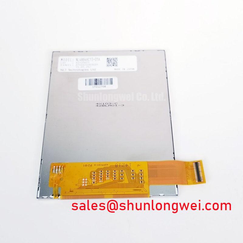
Set the replacement unit on an ESD-controlled bench and complete a visual inspection before connecting it to the host system. Examine the glass edge, flexible cable area, connector contacts, frame, polarizer surface, and any visible bonding region under uniform illumination. The factory information supplied for NL4864HC13-01A does not provide a construction drawing confirming a particular COG or TAB implementation, so those internal bonding details should be treated as unverified until supported by the manufacturer’s documentation.
A practical three-stage image check can use full-screen red, green, and blue patterns followed by black, white, and mid-grey images. Record dead areas, unstable rows or columns, colour non-uniformity, flicker, and changes that appear after warm-up. A 45 degree flashlight inspection can help reveal whether a faint image remains when the illumination path is not operating, but it cannot by itself distinguish every bonding, timing, or backlight condition. Compare the result with a known-good assembly whenever possible.
When a line defect is observed, inspect the connector seating and cable alignment before considering a glass-edge or driver-bond issue. Verify continuity without applying excessive mechanical force, then check the host timing and power sequence. A defect that changes when the cable is moved should be documented carefully, but movement should not be used as a repair method because it can increase damage to a flexible connection.
For a confirmed LVDS installation, inspect differential pair routing from the controller to the panel. The system designer should verify the interface’s specified differential impedance, pair skew, termination method, voltage range, and clock relationship from the original documentation. Oscilloscope testing should compare the replacement against the known-good unit while the enclosure, cable length, shielding, and industrial noise sources remain representative of service conditions.
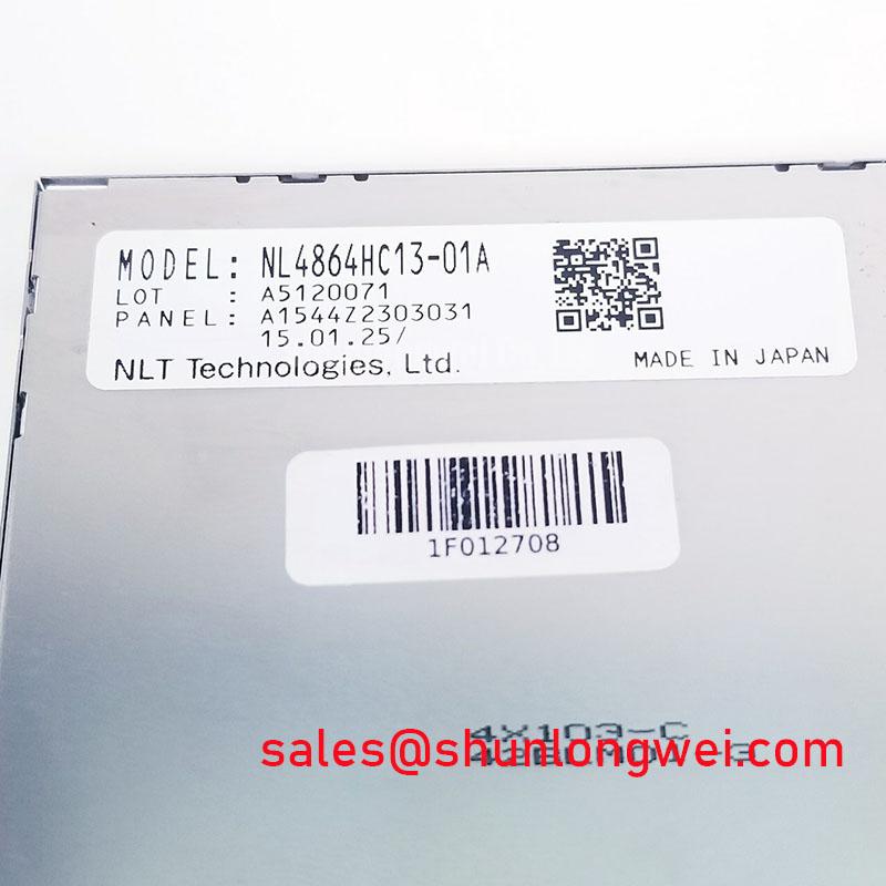
Finally, confirm that the mechanical frame does not press directly against the active display area and that the gasket remains seated after final tightening. Record the model marking, inspection date, visible condition, host equipment identification, and test pattern results in the maintenance file. This creates a useful acceptance record without assigning unverified electrical or lifetime claims to the NEC NL4864HC13-01A.