Content last revised on October 9, 2026
Mechanical and Environmental Suitability for Industrial and Heavy-Duty Equipment
| Model | EL640-200-U5 |
| Manufacturer | Planar |
| Product category | Industrial Grade LCD/HMI Panel |
| Panel technology | Electroluminescent panel |
| Specification status | Decoded baseline and standard form factor |
| Confirmed electrical ratings | Consult the original panel documentation before applying supply or drive values |
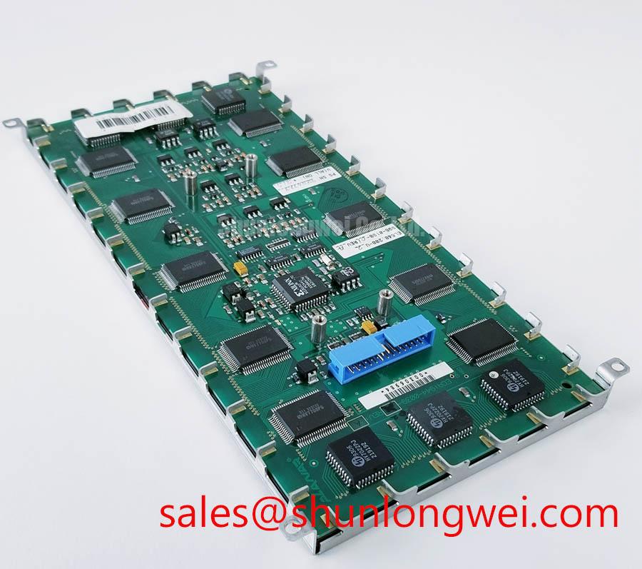
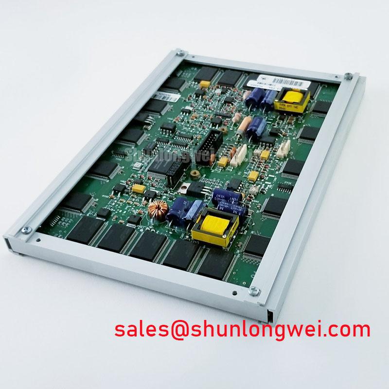
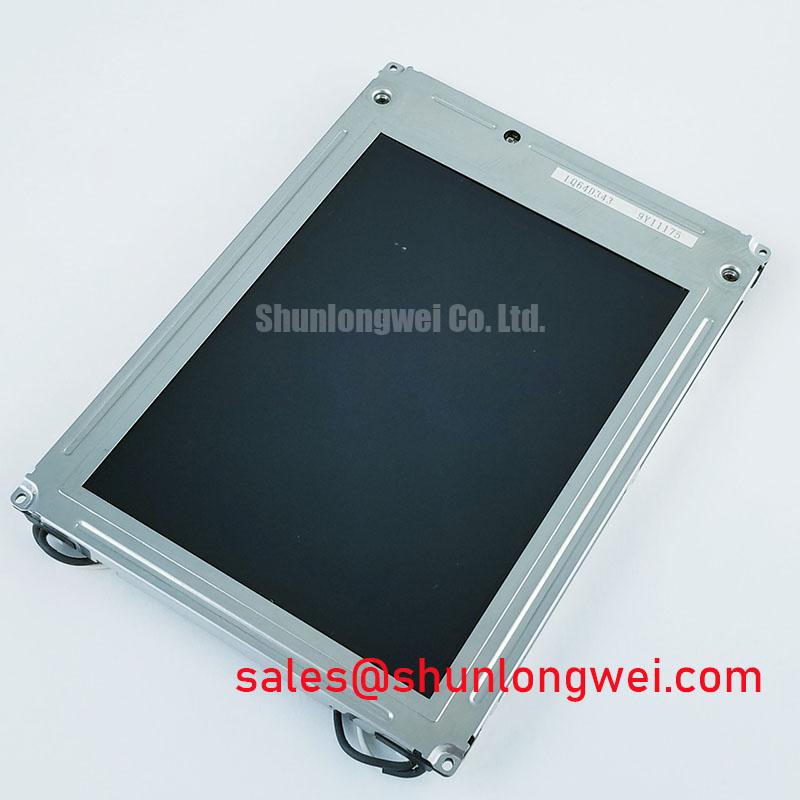
Begin a replacement inspection by comparing the removed panel’s connector position, mounting outline, optical surface, and system cable routing with the Planar EL640-200-U5. The available hardware identity establishes an industrial grade LCD/HMI panel using an electroluminescent panel construction, but the listed baseline does not establish a complete drive voltage, current, pinout, luminance, resolution, or backlight specification. Those values must remain system controlled during service evaluation.
Assess mechanical suitability by checking whether the replacement is supported evenly around its mounting perimeter and whether the enclosure prevents local pressure on the display face. An electroluminescent panel has no liquid crystal fluid that can freeze, so the cold-start investigation should focus on dielectric response, connector behavior, cable flexibility, mounting stress, and the host circuit’s start-up sequence. The EL640-200-U5 should not be described as carrying a confirmed 100G shock or 20G vibration rating unless those values appear in the applicable Planar data sheet or qualification report.
For equipment exposed to vibration, inspect the panel frame and bezel for signs of uneven compression after installation. A rigid fixing point beside a flexible section can transfer cabinet movement into the glass or connector area. The engineering objective is to distribute mechanical support without twisting the panel. The final mounting method remains determined by the host equipment drawing, gasket arrangement, fastener pattern, and environmental enclosure.
Cold-environment testing should use a controlled transition rather than an immediate full-load display test. Observe whether the panel starts consistently, whether brightness develops evenly, and whether the image remains stable as the host electronics reach their normal operating state. A sub-millisecond response characteristic, 179-degree viewing angle, or operation at minus 40 degrees Celsius should be treated as a qualification claim requiring a source specific to this exact model, not as a default property of every electroluminescent panel.
When a display appears dark after a shock event, separate optical failure from host-side power and control faults. Confirm that the equipment supply reaches the display interface, then compare the enable and drive timing with a known-good unit or the original service documentation. A loose cable, damaged latch, shifted frame, or failed driver stage can produce similar symptoms. Use an oscilloscope only with probes and grounding suitable for the circuit under test, especially when the panel is driven by a high-voltage alternating waveform.
For replacement planning, EL640.480-AA1 may be evaluated as a separate same-family display option where its mechanical outline, optical behavior, interface, and electrical requirements match the equipment documentation. It is a compatibility candidate, not an automatic substitute. The system engineer should compare the connector assignment, mounting dimensions, drive method, and image area before approving a change.
High-precision surgical navigation and ultrasound diagnostic displays require a stricter acceptance procedure because image uniformity and stable startup affect operator interpretation. The panel should be checked inside the complete display assembly, including the host controller, cable harness, shielding, and enclosure. A panel-level assessment cannot independently establish medical equipment compliance, EMC compliance, or clinical suitability.
Electroluminescent Dielectric Pin-Hole Defect Self-Healing versus Catastrophic Short-Circuit Screening
Screen the electroluminescent drive path by confirming waveform symmetry, isolation behavior, and current response under the host manufacturer’s approved test conditions. Electroluminescent panels commonly rely on alternating excitation rather than a simple low-voltage DC backlight, but the exact drive amplitude, frequency, connector assignment, and charge-recovery arrangement for the EL640-200-U5 must come from the matching technical documentation.
A nominal 180V to 240V peak drive range, zero net DC bias, thin-film ZnS:Mn emission layer, or self-healing dielectric behavior should not be assigned to this model without model-specific documentation. These are technology-level descriptions that may apply to selected electroluminescent constructions, not confirmed product data for every panel carrying a similar category label. During repair, the correct approach is to capture the original unit’s waveform and compare it with the replacement under controlled conditions.
Look for waveform imbalance, abnormal current rise, intermittent brightness, localized dark regions, or a protective shutdown from the driver. Each observation can have several causes, including connector contamination, drive-stage instability, cable insulation stress, panel damage, or an incorrect replacement interface. A current-limited test arrangement and an isolated measurement method help prevent a panel fault from becoming a host-board fault.
Backlight terminology also requires care. Do not assume that the EL640-200-U5 uses an LED constant-current driver, PWM dimming, a 200Hz to 1kHz control range, or a 50,000-hour backlight life figure. Those specifications belong to particular LED display assemblies and cannot be transferred to an electroluminescent panel without evidence. If the host system includes a separate LED module, the integrator should verify its open-load protection, short-circuit response, over-voltage behavior, dimming method, and diagnostic output from the driver documentation.
The complementary display assembly TCG070WVLPCANN-AN00 can be reviewed as a separate system-level reference when examining a host display topology, but it does not define the electrical requirements of the Planar panel. For a replacement evaluation, record the original connector pin functions, enable sequence, return paths, shielding arrangement, and any driver fault indication before reconnecting the panel.
⚡ Field Alert: Disconnect equipment power and allow the display driver to discharge before removing or inserting the panel cable, because an energized high-voltage AC drive can damage the connector interface or create a personnel hazard.
Optical inspection should include the anti-glare or anti-reflective treatment actually present on the replacement, viewing-angle behavior, uniformity at normal operating brightness, and reflections from surgical or ultrasound equipment lighting. AG and AR performance must be verified on the assembled unit because cover glass, bezel depth, protective films, and enclosure windows can change the observed result. Do not treat a general display category as proof of a particular optical coating.
For environmental acceptance, the service team can use Industrial Display and HMI Solutions as a practical reference when reviewing enclosure sealing, vibration transfer, thermal cycling, cable retention, and maintenance access. Any claimed shock, vibration, insulation, lifetime, safety, or EMC result still requires the relevant product or system qualification record. DisplayPort HBR packet behavior and HDMI signaling are separate digital interface subjects; their protocol characteristics can be reviewed through DisplayPort High Bit Rate packetized protocol and HDMI protocol references, but neither reference establishes the interface of this electroluminescent panel.