

Content last revised on September 10, 2026
Incoming Benchtop Inspection: COG/TAB Anisotropic Conductive Film Integrity
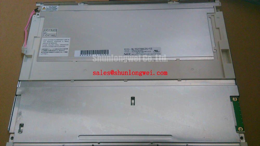
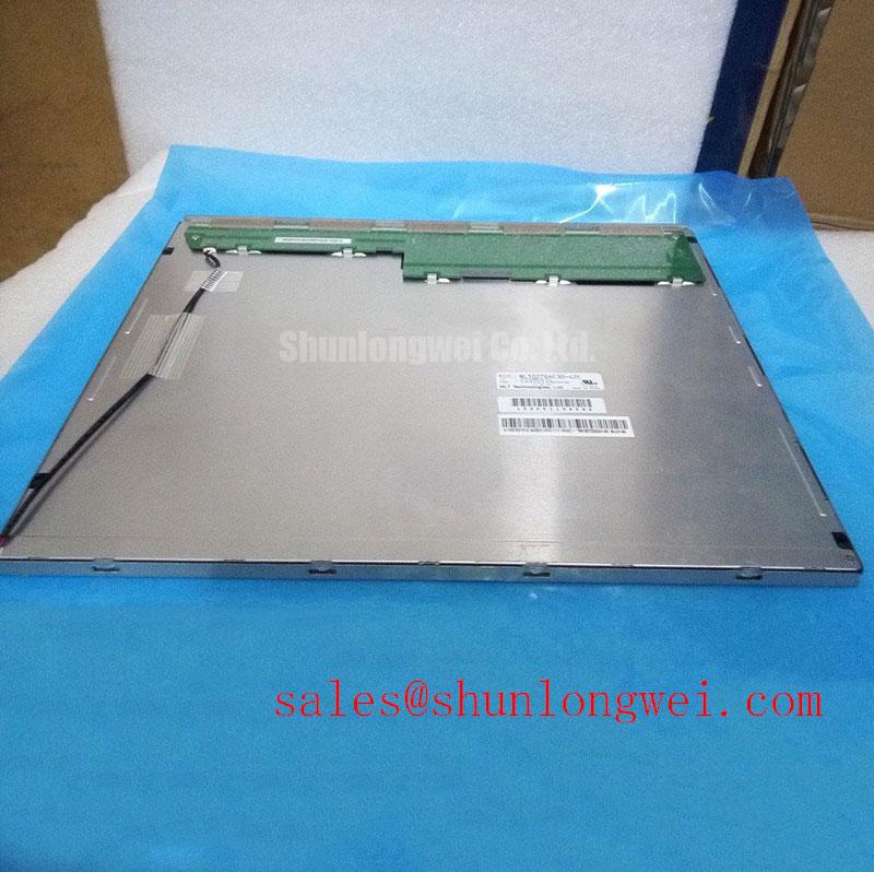
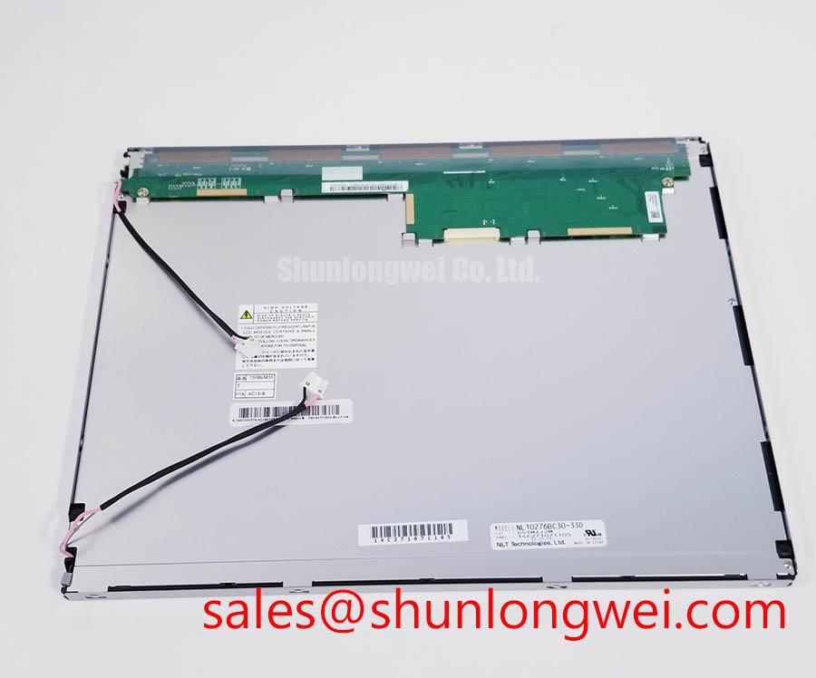
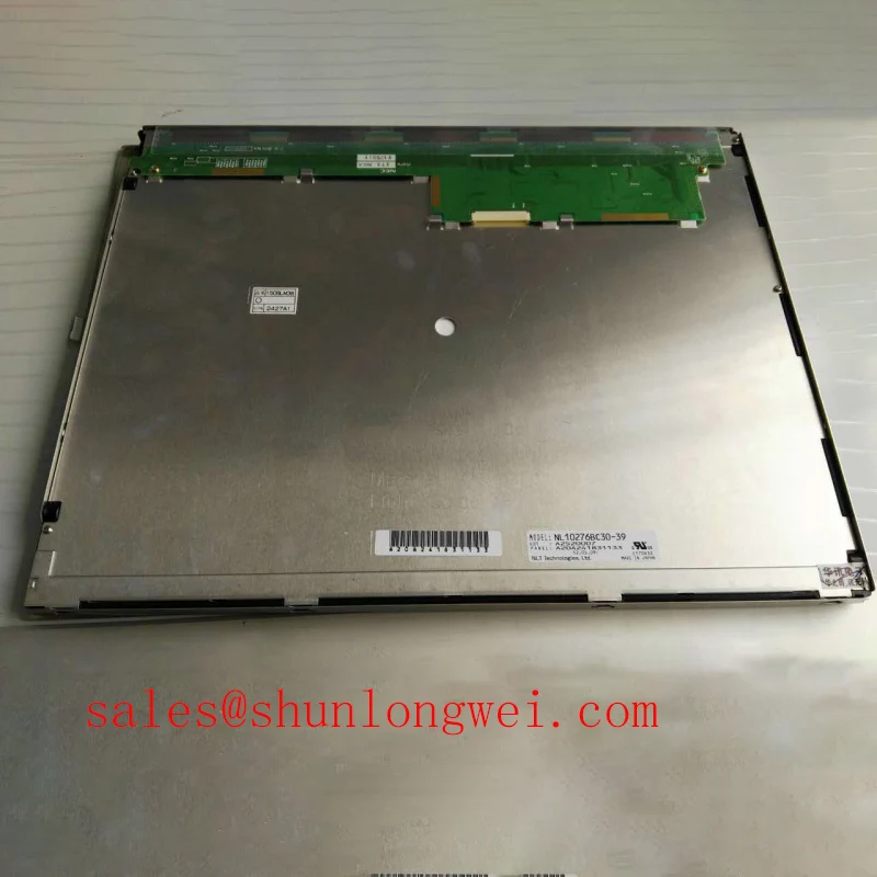
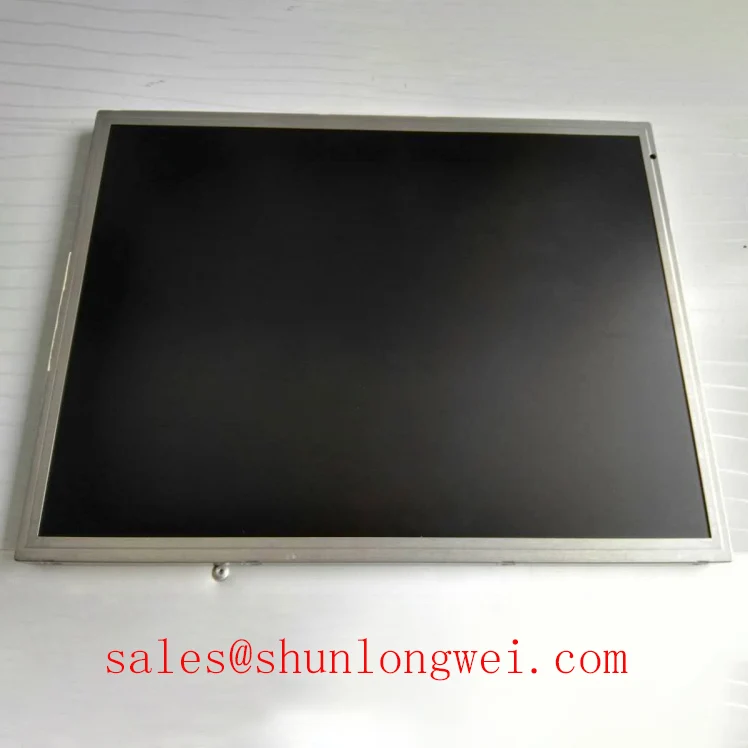
With the system fully isolated from power, inspect the NL10276BC30-39 display perimeter, front polarizer, rear housing, connector area, and flex-cable transitions under angled bench lighting before reconnecting it to the host controller. This NEC unit is an industrial TFT-LCD module.
Start with a controlled visual test rather than assuming that a black screen identifies the panel itself as the fault source. Examine the active area for pressure marks, vertical or horizontal line artifacts, irregular dark zones, edge discoloration, and localized changes in optical uniformity. A flashlight held at approximately 45 degrees to the display surface can help separate a visible but unilluminated image from a missing image signal. If menu graphics or raster content are faintly visible under external light, the fault investigation should continue through the host backlight supply path and associated control circuitry. If the image contains stable lines, blocks, or color regions while illumination is present, inspect the signal path and panel bonding area without treating any one symptom as conclusive proof of a specific internal failure.
COG and TAB bonding regions are not service points. They should be assessed only for externally visible stress, contamination, lifting, or damage around the panel edge. Do not press along the bezel or bonded edges to “restore” an intermittent image. Pressure can change the symptom temporarily while creating additional mechanical stress that obscures the original diagnosis.
For a practical color check, feed a known-good source through the original system interface and inspect full-screen red, green, blue, white, and black patterns. Compare the result with the original panel behavior where available. Uneven gray tracking, intermittent color loss, or image corruption during cable movement can indicate that the panel connector, mating harness, host timing circuit, or power sequencing should be examined. The official information provided for this model does not identify a panel input interface, supply rail, backlight type, dimming method, or PWM operating frequency. The system integrator should verify these requirements from the original panel documentation and host equipment schematic.
⚠️ Field Alert: Disconnect system power and allow stored energy to discharge before removing or inserting the display cable, because live connector handling can expose signal pins to unintended voltage levels.
For repair planning, compare mechanical fit, optical behavior, interface documentation, and host firmware expectations before evaluating another panel. The NL10276BC16-06 can be reviewed as a related NEC display option, but it should not be treated as a direct replacement until the original equipment requirements have been verified.
Viewing-Angle Assessment for Multi-Angle Console Screens
Check the display from the normal operator position first, then inspect it from above, below, left, and right while a neutral gray image is present. This exposes viewing-angle-dependent contrast change, color shift, brightness variation, and grayscale inversion that may be less apparent on a full-white screen. Such observations help distinguish panel optical behavior from glare caused by the enclosure window, screen contamination, or reflected ambient light.
The supplied official factory information identifies the NL10276BC30-39 as a TFT-LCD module, but it does not specify whether the liquid-crystal mode is Super-IPS, MVA, TN, or another architecture. It also does not provide a numeric viewing cone, anti-glare surface specification, contrast ratio, luminance rating, or chromaticity data. A claimed 85°/85°/85°/85° viewing specification must therefore not be assigned to this exact model without the applicable NEC documentation.
Design Consideration: multi-angle console viewing should be assessed with the complete assembly in place. A protective cover lens, touch overlay, bonding layer, bezel depth, and ambient illumination can all alter the usable viewing result seen by an operator. Where the equipment is evaluated for a marine radar or navigation bridge console, engineers should check readability under the actual enclosure geometry and surrounding light conditions rather than relying on panel technology labels alone. Environmental sealing, corrosion resistance, and approval requirements remain responsibilities of the complete equipment assembly and cannot be inferred from the display module category.
Surface reflections often resemble contrast loss. Before condemning the panel, clean only by the equipment manufacturer’s approved method, inspect the cover window for haze or scratches, and compare the image with the display temporarily shielded from direct light. If image quality changes markedly with viewing position but the electrical picture remains stable, the result may be optical and should be compared against a known-good unit or the original display specification.
Design Consideration: if the host design uses PWM brightness control, the brightness response should be checked across the intended dimming range with the installed driver and enclosure. Audible noise, visible shimmer, camera-band artifacts, and nonuniform low-brightness behavior are system-level observations. The display module’s supplied factory details do not establish a permitted PWM frequency, duty-cycle range, or dimming transfer characteristic for this model.
Backlight Supply Path and Insulation Verification
When the panel produces a faint image under a flashlight but no normal illuminated picture, begin at the host equipment’s backlight enable signal, brightness control signal, supply connector, and driver output documentation. Confirm that the driver receives its expected input conditions from the original system design, then compare the output behavior against a known-good channel where the equipment architecture permits it. This sequence avoids applying assumptions about the backlight technology inside the NL10276BC30-39.
The available official factory data does not state whether this NEC TFT-LCD module uses a CCFL or LED backlight, and it does not publish lamp striking voltage, driver current, insulation level, dimming ratio, acoustic-noise behavior, or backlight lifetime. Values such as 1500 to 1650 Vrms, 1000:1 PWM dimming, and 50,000-hour brightness-life statements must not be represented as specifications for this model without a matching manufacturer document.
Design Consideration: high-voltage testing of a legacy backlight circuit requires equipment-specific procedures, correctly rated probes, and an understanding of the driver topology. A secondary-side measurement made with an unsuitable instrument can be unsafe and can also load the circuit enough to change the observed result. If the original display documentation identifies a lamp-driven architecture, technicians should follow the host manufacturer’s isolation and measurement method. If the documentation identifies an LED driver, evaluate constant-current operation, enable sequencing, and thermal conditions within that documented system architecture.
Local heating around a driver board, connector, or cable termination should be examined in context. It may arise from a degraded connection, a power conversion issue, restricted enclosure airflow, or another condition external to the panel. Avoid treating temperature rise as a direct statement about panel health. Inspect cable seating, contact condition, board damage, and the relationship between the symptom and commanded brightness before deciding whether the display module requires replacement.
For related NEC display-family review during power-path troubleshooting, the NL10276BC30-24D may provide a useful comparison point. Its electrical and mechanical documentation must still be checked independently; shared manufacturer naming does not establish interchangeable backlight or signal characteristics.
Preventing Frame Lag and Image Smearing in Cold or Outdoor Installations
Run a moving grayscale pattern and menu-transition test after the equipment has stabilized at its actual operating temperature. Observe whether motion trails, delayed updates, incomplete contrast transitions, or temporary nonuniformity change as the enclosure warms. Liquid-crystal response is temperature dependent, but the supplied official factory data for NL10276BC30-39 does not provide response time, operating-temperature range, storage-temperature range, thermal-cycle qualification, perimeter-seal construction, or image-retention limits.
For that reason, a minus 30°C to plus 85°C operating claim cannot be attributed to this specific module from the stated information. Cold-storage, outdoor, and high-temperature equipment evaluations should use the original NEC environmental documentation together with the finished equipment requirements. The panel is only one part of the thermal system; the enclosure, heater strategy where used, front window, mounting method, controller location, and internal airflow influence the observed display behavior.
Design Consideration: when frame lag or smearing is reported after exposure to cold, allow the complete device to return to a controlled operating condition and repeat the same test image before making a replacement decision. Compare behavior across multiple image patterns and check whether the host controller output remains stable. A corrupted or unstable input signal can resemble a panel response issue, especially where the display cable runs near servo drives, switching power supplies, contactors, or other noise-generating equipment.
Signal integrity should be evaluated from the interface actually specified for the original panel. If the system uses differential video signaling, the cable pair routing, connector retention, shielding approach, termination arrangement, and clock quality should be checked against the host design documentation. Do not assign an interface type, impedance target, or timing requirement to this NEC model where the relevant factory specification has not been supplied. The system engineer should verify peak signal quality against a known-good signal path and assess noise coupling with the equipment operating normally.
For broader context on panel selection, integration variables, and common industrial TFT-LCD service questions, consult The Ultimate Guide to Industrial TFT LCD Technology. Any final installation decision for the NL10276BC30-39 should remain tied to the original equipment documentation, physical fit, connector definition, power requirements, and validated on-screen performance.