Content last revised on October 9, 2026
Incoming Benchtop Inspection: COG and TAB ACF Integrity
| Model | LQ121S1DG11 |
| Manufacturer | Sharp |
| Product category | Industrial Grade LCD/HMI Panel |
| Display technology | TFT LCD active matrix color display module |
| Specification status | Decoded baseline, standard form factor |
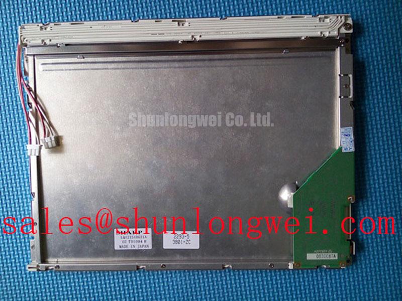
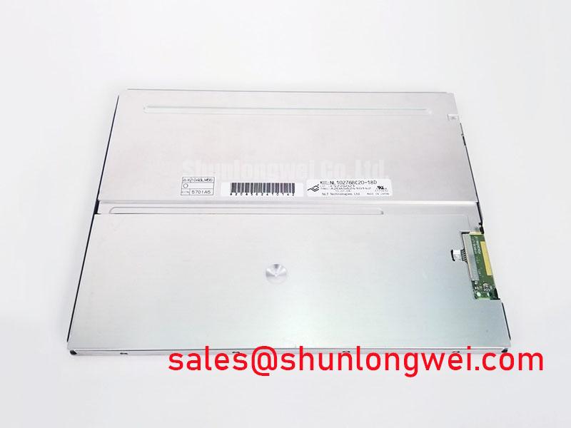
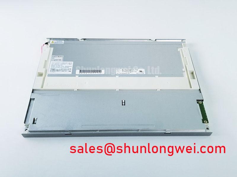
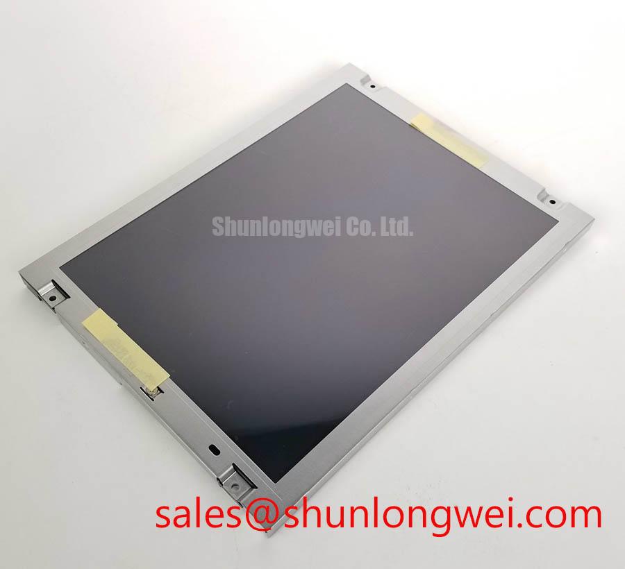
Begin the incoming inspection of the LQ121S1DG11 with the display disconnected from the equipment and positioned on a protected bench. Check the bezel, glass edge, flexible connections, and visible bonding areas for impact marks, lifted edges, contamination, or uneven mechanical pressure. The product is identified as a Sharp TFT LCD active matrix color display module; dimensional, interface, resolution, and supply details should be matched with the original equipment documentation before installation.
Use a standardized primary color sequence consisting of red, green, and blue screens, followed by white and black where the test controller supports them. Look for persistent vertical lines, localized color loss, unstable regions, and areas that respond differently during image changes. A defect that remains fixed while the backlight illumination is uniform deserves separate attention from a dark region that follows the lighting system.
A flashlight held at approximately 45 degrees can help distinguish optical illumination problems from pixel or driver line defects. With the panel displaying a dark image, observe whether a shadow changes with the flashlight angle or remains fixed within the image structure. This is a practical screening method rather than a substitute for a panel service procedure. It can help direct the next inspection toward the backlight path, display electronics, or the bonded driver region.
Temperature testing requires controlled handling. At sub zero conditions such as −20°C to −30°C, liquid crystal response can become visibly slower and gray transitions may elongate. Treat this as an engineering evaluation condition, not as an LQ121S1DG11 operating rating. If a cabinet uses a heater or controlled warm up sequence, the system engineer should confirm that condensation is prevented before enabling the display and that the panel reaches a stable condition before judging image response.
Backlight Architecture, Constant Current Driving, and Dimming Evaluation
Identify the installed backlight architecture before applying power to a replacement panel. Do not interchange a high voltage cold cathode fluorescent lamp circuit with a constant current LED circuit based only on connector appearance. The original display documentation and equipment wiring determine the required backlight supply, enable signal, dimming method, and protection behavior.
For a system using LED illumination, the driver should regulate current through the backlight path and respond correctly to open load, short circuit, overvoltage, and thermal fault conditions where those functions are provided by the driver. PWM dimming performance should be checked at the actual controller and driver interface. A claimed dimming ratio, including 1000:1, must be treated as a system level characteristic unless it is explicitly stated in the relevant panel or driver documentation.
For equipment being repaired from an older CCFL design, cold ignition behavior belongs to the inverter and lamp assembly rather than the LCD image panel itself. High voltage ignition measurements require suitable probes, spacing, guarding, and service procedures. The engineer should confirm whether the replacement configuration retains the original backlight technology or requires a separately validated conversion.
Brightness aging should be assessed from the complete display assembly, including driver current, thermal conditions, duty cycle, enclosure airflow, and operating brightness. A 50,000 hour half brightness value must not be assigned to this Sharp model without a corresponding manufacturer specification or test source. Record brightness uniformity and driver fault indications during controlled maintenance checks instead of using an assumed lifetime curve.
⚠️ Maintenance Note: Inspect the cabinet airflow path and panel sealing gasket during scheduled service because dust accumulation or a compressed gasket can increase thermal stress and create uneven mechanical loading.
Dynamic Contrast and Liquid Crystal Temperature Tracking
Evaluate grayscale behavior at the actual viewing angle and ambient illumination used by the instrument. TN, IPS, and MVA are different liquid crystal architectures, so a replacement selection should not be judged by a generic viewing cone or contrast claim. The available product definition identifies the LQ121S1DG11 as a TFT active matrix color module, but it does not establish a particular liquid crystal mode, viewing angle specification, or contrast ratio.
Display a stepped grayscale pattern and observe black level stability, near white uniformity, and any inversion that appears when the operator moves above, below, or to either side of the normal viewing axis. Compare the result at room temperature and after the panel has reached the intended enclosure temperature. Temperature changes can influence liquid crystal viscosity and transition behavior, making a panel appear slower or less consistent during cold startup.
High ambient light makes surface reflection a significant service concern. Confirm whether the installed front surface uses an anti glare or anti reflective treatment from the original panel documentation rather than assuming that every TFT module has the same optical finish. A glossy replacement can produce more reflected light even when its electronic image signal is correct.
For optical comparison, use the same image files, viewing distance, instrument illumination, and camera exposure. This avoids confusing an optical measurement change with an actual display fault. Sharp’s industrial display resources at Sharp Devices Europe Industrial Display Solutions and the Sharp Display Solutions Official Portal provide useful manufacturer context for industrial display evaluation.
Suppressing Pixel Jitter and Horizontal White Lines Near Motor Drives
When pixel jitter or horizontal white bands appear near a variable frequency motor drive, begin with cable routing, shield termination, connector seating, and the separation between display wiring and switching power conductors. Do not attribute the symptom to the LCD glass alone. A disturbed LVDS or TTL signal path, shared return impedance, grounding arrangement, or radiated noise can produce similar visual effects.
Use the original cable construction and pin assignment as the reference. LVDS pairs should remain together through the route, with their differential geometry preserved as far as the equipment layout permits. A nominal 100 Ω differential impedance is a common design target for LVDS interconnects, but the correct value and termination arrangement remain determined by the transmitter, receiver, cable, and panel interface documentation.
A shielded FFC or cable should be bonded according to the equipment grounding architecture rather than connected at arbitrary points. Common mode ferrites may be evaluated as a system level electromagnetic compatibility measure when testing shows a conducted or radiated interference path, but they are not confirmed as an integrated feature of the LQ121S1DG11.
During troubleshooting, compare the display clock and data at the panel interface with a known good operating condition. Check whether the disturbance follows motor drive acceleration, deceleration, or switching state. A clock margin problem can arise from signal integrity, grounding, cable movement, temperature, or controller timing. The correct remedy should be selected after observing the waveform and verifying data hold behavior across the intended industrial temperature window.
For replacement planning, engineers evaluating a same size or same resolution service option can review LQ121K1LG61 as a separate device for interface and mechanical comparison. A related Sharp display option may also be reviewed through LQ123K1LG03 when assessing a complementary display solution. For broader interface, optical, and field troubleshooting context, consult The Ultimate Guide to Industrial TFT LCD Technology.