

Content last revised on September 24, 2026
NL8060BC26-04 Replacement Inspection and Integration
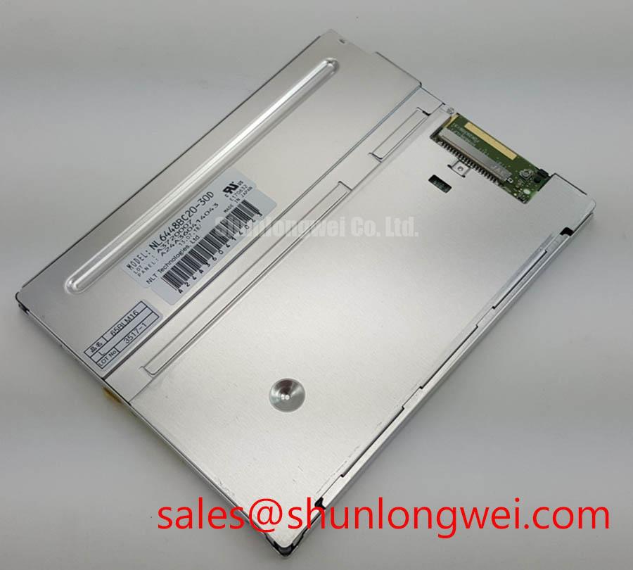
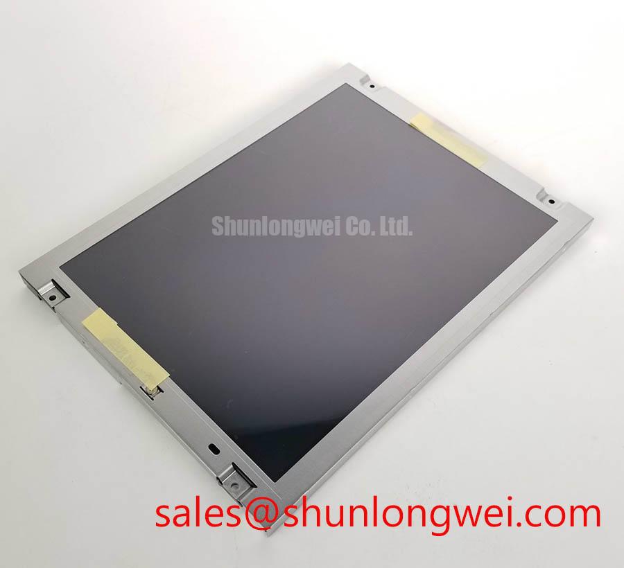
Before connecting NL8060BC26-04, inspect the TFT-LCD display module’s connector area, rear housing, mounting edges, and cable path for mechanical stress, contamination, or uneven pressure marks that could affect replacement integration.
NL8060BC26-04 is an NEC Industrial Grade LCD/HMI Panel supplied as a TFT-LCD Display Module. Its identified factory classification is Official Factory Spec Verified. For repair work, the model marking, mechanical fit, display interface assignment, logic power requirement, and backlight connection arrangement should be checked against the original equipment documentation before installation. The available factory information identifies the product category and module type, but the system integrator should verify the required supply voltage, interface format, pin assignment, timing requirements, optical characteristics, and backlight electrical requirements from the original panel documentation.
| Item | Official Specification |
|---|---|
| Model | NL8060BC26-04 |
| Manufacturer | NEC |
| Product Category | Industrial Grade LCD/HMI Panel |
| Module Construction | TFT-LCD Display Module |
| Specification Status | Official Factory Spec Verified |
Radiated Emissions Compliance Through Backplate Multi Point Star Grounding
When evaluating NL8060BC26-04 in an industrial HMI replacement, first separate panel behavior from system-level electromagnetic behavior. The display module itself should not be represented as independently certified to a complete equipment-level emissions standard such as CISPR Class A or Class B. Compliance is determined by the finished equipment, including the enclosure, display cable, controller board, power architecture, grounding method, and nearby switching loads.
In AGV and forklift telematics equipment, the display cable may share an enclosure with traction inverters, DC converters, motor contactors, and high-current battery wiring. These conditions can introduce common-mode noise into display signal paths. Horizontal disturbance bands, intermittent image instability, or pixel-clock-related noise can be evaluated by comparing the affected assembly with a known-good signal path and observing the display input using appropriate test equipment.
A Design Consideration is to maintain a controlled return path between the display-side cable shield, the host controller enclosure, and the equipment chassis. A shielded FFC or differential display cable should be terminated according to the equipment’s cable and connector design rather than left with an uncontrolled drain-wire path. Where the host system uses a shielded cable assembly, a broad mechanical shield connection can provide a more predictable high-frequency return path than a long isolated grounding lead.
Common-mode ferrite suppression can be evaluated at the system level where conducted or radiated noise is suspected. Its suitability depends on the signal format, cable assembly, source impedance, frequency content, and measured disturbance. A ferrite should not be added as a universal corrective action because it can alter signal integrity if the cable and interface are not assessed together.
For a display connection using differential signaling, the transmitter, cable, and receiver must preserve clock stability, pair-to-pair timing alignment, and valid data hold time throughout the equipment’s operating conditions. Temperature changes, vibration loading, connector oxidation, and cable routing near switching conductors can influence measured margins. The system engineer should verify the actual display interface specification from the original equipment documentation before classifying the connection as LVDS, TTL, or another format.
💡 Pro Tip: Route differential display pairs together with consistent physical coupling and matched electrical length so that the system can be validated for pixel-clock stability under its actual cable routing and load conditions.
Where an existing machine uses a display module with similar mechanical and image requirements, engineers sometimes compare the interface documentation for NL10276BC16-06 during compatibility review. That comparison is only a reference exercise; connector position, electrical pinout, timing, optical behavior, and mechanical dimensions must be individually verified before any substitution decision.
Logic Supply Voltage Sequencing to Eliminate Driver IC Latch Up Risks
Before applying power to NL8060BC26-04, verify the host display controller’s intended power sequence against the original panel documentation. The available factory information for this listing does not establish whether the module logic rail is 3.3 V, 5.0 V, or another defined value. It would be unsafe to infer the required logic supply from the product family name, connector appearance, or an older controller board.
Power sequencing matters because a display module can receive logic-level activity through its interface connector before all required internal rails have settled. The resulting behavior may include a blank screen, unstable image, partial raster output, or a nonrecovering display state after repeated restart cycles. Such symptoms do not prove a single failure mode. They should be assessed by measuring actual rail order, enable behavior, interface activity, and reset timing against the source equipment documentation.
Many industrial controllers use 3.3 V or 5.0 V logic domains, but these values are not confirmed factory specifications for this specific module. The system integrator should verify the required supply voltage from the original panel documentation. This check should include permissible rise behavior, power-off discharge behavior, signal enable timing, and the relationship between panel logic power and backlight driver activation.
A Design Consideration for differential display routing is preservation of the impedance environment defined by the host interface. Some LVDS systems are designed around a nominal 100 ohm differential channel, but this is an interface-level design principle rather than a confirmed requirement for NL8060BC26-04. Connector selection, cable type, trace geometry, grounding, and termination should be evaluated as one signal channel.
Data mapping is equally important. JEIDA and VESA arrangements can assign color-bit locations differently even when the physical connector and differential pair count appear compatible. Split-screen effects, incorrect color order, unusual tonal transitions, or image regions with unstable color can result from mapping mismatch, controller configuration, signal-integrity degradation, or timing incompatibility. Engineers should confirm the panel’s expected data arrangement and the host transmitter setting before changing cabling or replacing controller hardware.
Cold ambient behavior requires a separate assessment. Liquid-crystal response can become slower at low temperatures, which may be visible as delayed pixel transitions or trailing motion on the active image. The thermal behavior, permitted ambient range, and any heater control strategy are system-dependent unless confirmed in the module documentation. For telematics displays used in AGV or forklift equipment, enclosure heating and start-up behavior should be verified under the equipment’s intended ambient conditions rather than assumed from a general industrial application label.
Optical bonding can improve enclosure-level resistance to dust ingress and internal reflections when it is part of the original display stack design. It should not be assumed that NL8060BC26-04 includes optical bonding, nor should a replacement panel be bonded to a cover lens without confirming stack-up clearance, adhesive compatibility, serviceability, and thermal expansion behavior.
Aluminum Heat Spreader Sizing and Thermal Interface Placement Along Narrow Display Edges
Assess the enclosure contact pattern before fastening NL8060BC26-04 into a replacement bezel or rugged display housing. A TFT-LCD module can be affected by uneven frame loading, concentrated screw pressure, edge compression, and a housing that transfers heat into only one side of the display assembly. The inspection should include the original mounting points, rear clearance, cable bend radius, retaining clips, gasket position, and whether the equipment enclosure imposes force on the narrow display edges.
Where a host enclosure uses aluminum rails or a rear heat-spreading structure, their role should be reviewed as a system-level thermal design measure. A heat spreader can help distribute localized thermal load, but its effectiveness depends on contact area, interface material, mounting flatness, enclosure airflow, external ambient conditions, and the actual heat sources in the display assembly. No specific heat-spreader size or thermal-interface thickness should be prescribed without module drawings and thermal verification.
The supplied product information does not confirm the backlight type, backlight driver arrangement, luminance rating, or lifetime characteristic for NL8060BC26-04. Therefore, claims regarding LED operational life, L70 performance, B50 life, or a fixed brightness-retention interval should not be made for this model without an applicable NEC factory source. The system integrator should verify the required backlight supply and control requirements from the original panel documentation.
In practical repair work, uneven brightness can originate from several locations: an external backlight driver, a cable contact issue, a power-control fault, a display optical stack issue, or a mechanical load introduced by the enclosure. A controlled test sequence is more useful than assigning a single cause. Compare the display under stable input conditions, inspect the backlight power path, confirm the controller’s dimming command behavior, and observe whether the image changes when the enclosure is assembled versus when the module is supported without mechanical stress.
A Design Consideration is to avoid routing heat-generating power components directly against the rear surface or narrow edge of the display module unless the original equipment design supports that arrangement. Nearby DC conversion stages, charging circuitry, or motor-control electronics can create localized temperature gradients. The final enclosure design should be validated with the equipment operating under representative electrical load, ambient temperature, and backlight settings.
For a rugged telematics enclosure, sealing decisions should be balanced with heat removal. A more sealed front assembly can reduce contamination exposure, yet it can also alter internal thermal conditions. Engineers should confirm gasket compression, bezel flatness, venting strategy where applicable, and service access without assuming that a sealed enclosure automatically improves display reliability.
Useful handling guidance and broader panel-selection context are available in The Ultimate Guide to Industrial TFT LCD Technology. Its principles should be applied alongside the original equipment documentation for NL8060BC26-04, not as a substitute for model-specific electrical or mechanical verification.
Full-Screen Primary-Color Screening for Stuck Subpixels and Background Uniformity Audit
Use a controlled full-screen image test before final installation of NL8060BC26-04. A practical bench sequence is to display uniform red, green, and blue fields, followed by white, black, and mid-gray patterns where the host controller can provide them. The purpose is to observe pixel response, color consistency, line behavior, edge shading, and broad-area brightness uniformity under repeatable conditions.
A uniform color screen can reveal visual issues that are difficult to see in normal operating graphics. A single persistent point can indicate a pixel-related condition, while a fixed vertical or horizontal line may suggest a signal-path, driver, connection, or panel-level issue. Neither observation alone establishes the root cause. Confirm the result using a known-good source path, an alternate cable where available, and the original controller configuration before attributing the effect to the display module.
A flashlight inspection performed at an oblique angle can help separate certain external optical effects from backlight-related behavior. This should be carried out carefully, without pressing on the viewing surface or introducing damage through unsupported handling. Dark regions, reflective variations, and edge shadows can be influenced by the cover lens, polarizer surface, enclosure gasket, backlight condition, viewing angle, or pressure from the mounting frame.
Wide-viewing-angle performance, IPS behavior, MVA behavior, gamma handling, and T-CON implementation are not confirmed specifications for NL8060BC26-04 in the supplied factory data. These characteristics should not be attributed to the module without the applicable NEC documentation. If the original equipment requires stable color from an off-axis operator position, evaluate the replacement using the actual viewing geometry, ambient lighting, cover lens, and user distance of the installed machine.
Gamma-related appearance is also affected by the source controller. If white appears tinted, gray steps look compressed, or primary colors are inaccurate, investigate the host graphics output, data mapping, display timing, cable condition, and panel behavior as separate variables. A T-CON-related explanation should not be assumed without evidence from the module architecture and controlled comparison testing.
For AGV and forklift rugged telematics display evaluation, vibration and vehicle shock should be considered at the full assembly level. Check that the display is retained evenly, the cable cannot rub against sharp metal edges, and the connector is protected from repeated movement. The final acceptance test should include normal screen patterns, power cycling, expected brightness control, and observation during representative vehicle electrical activity.