


Content last revised on September 10, 2026
NEC NL6448BC20-35D Incoming Inspection and Application Boundary
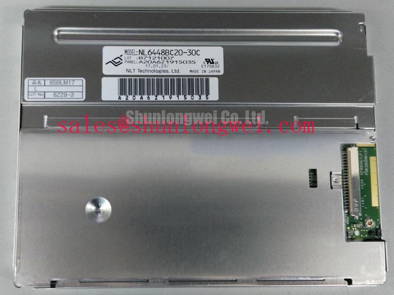
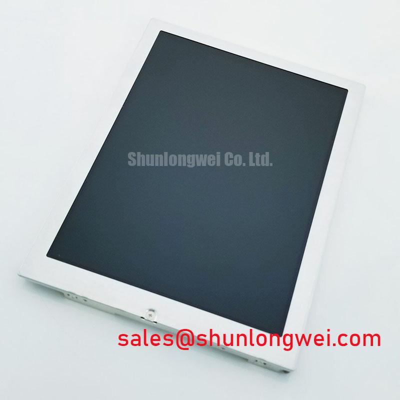
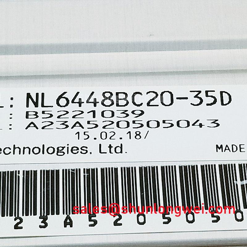
At incoming inspection, place the NEC NL6448BC20-35D on an ESD-safe work surface, check the module label against the purchase record, and inspect the TFT-LCD assembly for bezel deformation, glass damage, connector contamination, and visible FPC stress before applying power. The supplied factory context identifies this part as an Industrial Grade LCD/HMI Panel manufactured by NEC, packaged as a TFT-LCD Display Module, with an official factory specification status.
This identification is important when replacing a display in an industrial HMI, monitoring console, or marine radar and navigation bridge console. A display module is not interchangeable solely because its mechanical outline appears similar. The system integrator should verify the original equipment documentation for active display area, resolution, interface type, connector position, backlight arrangement, logic supply, timing, and mounting geometry before installation. Those values are not included in the supplied official parameter set and should not be inferred from the model number.
| Parameter | Official factory information supplied |
| Model | NL6448BC20-35D |
| Manufacturer | NEC |
| Product category | Industrial Grade LCD/HMI Panel |
| Construction category | TFT-LCD Display Module |
| Specification status | Official Factory Spec Verified |
For a repair engineer, the first practical decision is whether the removed display and the replacement belong to the same electrical and mechanical configuration. Record the original panel’s label information, connector markings, backlight harness, and controller settings. Photographing the installed cable path before disassembly can prevent a later reversal of the data cable or backlight connector. If the original equipment documentation specifies a particular logic voltage or signal mapping, use that document as the controlling reference.
For a same-size or same-resolution evaluation, the NL10276BC16-06 may be reviewed as a separate display option, but a direct replacement decision requires confirmation of the active area, mounting points, connector pinout, optical performance, and timing compatibility. A visually similar panel should not be treated as a drop-in substitute without those checks.
High-Nits Edge-Lit LED Rail Thermal Dissipation and Light Guide Preservation
The supplied official data does not confirm that the NL6448BC20-35D uses an edge-lit LED backlight, a PMMA light guide plate, a specified luminance level, or an L70 or B50 life rating. These subjects can be relevant during system integration, but they must remain design considerations unless the original NEC documentation for this exact revision provides the corresponding values. The system integrator should verify the backlight technology from the panel data sheet and the installed harness before selecting a driver or modifying the chassis.
In a high-brightness console, heat management starts with the enclosure rather than with assumptions about the panel’s internal construction. Inspect whether the host chassis provides a clear thermal path around the display perimeter. Any aluminum spreader or mounting rail should be positioned according to the mechanical drawing, avoiding pressure on the glass, FPC, connector, and visible bezel. The purpose of the thermal path is to reduce localized heat accumulation near the display edges while preserving the manufacturer’s mechanical clearances. Final thermal performance should be checked with the panel operating in the completed enclosure, not on an open bench alone.
For a marine radar or navigation bridge console, sunlight exposure, sealed enclosures, and limited airflow can change the temperature seen by the display. Salt-laden air also makes connector protection and enclosure sealing significant system-level considerations. The panel itself should not be described as independently rated for a marine environment unless the applicable NEC specification states that rating. Designers should evaluate the complete enclosure, gasket arrangement, corrosion control, and service access as one assembly.
Cold operation requires a similar evidence-based approach. Liquid crystal response can change as ambient temperature falls, which may appear as slower grey-to-grey transitions, image trailing, or delayed visual stabilization. The correct response is to verify the specified operating temperature range and cold-start behavior in the original panel documentation. If the host system uses a heater strip, its control strategy should be validated with the display supplier’s temperature limits and with measured image performance. Do not assign a universal heater setting to this model without a documented thermal test.
The backlight supply also requires confirmation. The supplied information does not identify whether this particular unit requires a CCFL inverter or a constant-current LED driver. The system integrator should verify the required backlight technology, voltage, current, enable signal, dimming method, and connector pinout from the original panel documentation. The related NL10276BC30-24D can be reviewed as a separate display solution when assessing related drive and supply topologies, but it should not be assumed to share the NL6448BC20-35D interface.
Backlight Ignition and Dimming Debugging at the System Boundary
High-voltage CCFL ignition values, LED PWM ratios, acoustic noise behavior, and long-term brightness decay are not confirmed in the supplied factory data for the NL6448BC20-35D. A repair bench should therefore begin by identifying the installed backlight architecture. Look for the original inverter or LED driver, note the connector labels, and compare the electrical markings with the panel documentation. A driver that powers a visually similar display may still apply an unsuitable voltage, current, enable sequence, or dimming waveform.
If the original assembly uses a CCFL inverter, ignition should be evaluated through the approved test method for that inverter and panel combination. High-voltage probing requires suitable equipment, insulated fixtures, and a controlled discharge procedure. Intermittent ignition, uneven illumination, or audible noise should be investigated across the input supply, enable line, inverter output, lamp harness, and mechanical seating rather than attributed to a single component immediately. The replacement panel should not be connected to an unverified inverter simply because the connector appears compatible.
If the original assembly uses an LED backlight, measure the driver’s constant-current behavior and inspect the dimming control under the actual controller configuration. The requested PWM range of 200 Hz to 1 kHz is an integration target, not an official specification supplied for this model. Designers should select a dimming frequency based on the driver, camera exposure requirements, visible flicker assessment, acoustic behavior, and the host controller’s timing capability. The complete system should be checked for brightness ripple during minimum and maximum commanded levels.
Brightness uniformity should be assessed after the panel has reached a stable operating condition. Use full-field white, black, red, green, and blue patterns to identify edge shading, intermittent zones, stuck pixels, and backlight nonuniformity. A dark-field inspection is useful for separating pixel-related defects from optical or mechanical shading. Record the test pattern, ambient condition, driver setting, and warm-up state so that a later comparison remains meaningful.
There is no supplied source establishing a specific 50,000-hour half-brightness rating or MTBF value for this exact model. Such figures should only be published when present in an applicable NEC specification or an authoritative qualification document. For field service, a more useful procedure is to compare the replacement against the removed panel under identical drive settings, then document luminance, uniformity, flicker, and startup behavior without presenting those local measurements as a factory life guarantee.
💡 Bench Tip: Disconnect power before inserting or removing the display cable, maintain ESD protection, and keep the FPC fully aligned with the connector lock to avoid stressing the contact area.
Chassis Fastener Loading and Optical Mura Control
The NL6448BC20-35D is identified as a TFT-LCD Display Module, but the supplied official parameter set does not include its bezel drawing, chassis envelope, screw specification, or permitted fastening torque. The host equipment’s mechanical drawing must therefore control the installation. Before tightening the frame, confirm that the panel rests evenly on its intended support surfaces and that no screw, bracket, cable, or gasket is pressing directly against the active display area.
Uneven chassis loading can produce visible optical nonuniformity, local darkening, bright patches, or pressure-related image changes. These symptoms do not prove one single mechanical cause. Inspect the bezel for distortion, compare the display with the fasteners relaxed, and check whether the optical pattern changes when the frame is repositioned according to the equipment drawing. The panel should be evaluated in its final orientation because gravity, vibration, cable routing, and enclosure stiffness can influence the load path.
An M3 fastener torque range of 0.35 to 0.45 N·m is not an official NL6448BC20-35D specification supplied here. It must not be treated as a mandatory value for this model. If the equipment manufacturer provides a torque requirement, follow that document. If no value is available, the mechanical engineer may establish a controlled starting point through a fixture test, using a calibrated driver and observing optical uniformity, bezel strain, and retention after vibration screening. The final setting should be confirmed by the responsible system designer.
Cross-pattern tightening can help distribute frame loading when the chassis drawing supports that method, but the sequence remains a design consideration rather than a panel-specific factory requirement. Tighten progressively while checking that the FPC does not become trapped and that the connector remains free from bending force. Where the display is exposed to vibration or shock, use the original mounting provisions and avoid adding rigid clamps that transfer enclosure movement directly into the glass or cable termination.
FPC routing deserves a separate inspection. Keep the bend path within the supplier’s documented limits, avoid sharp creases, and provide strain relief through the chassis rather than through the connector body. A cable that appears electrically functional during a short bench test may still become intermittent after repeated service access if the locking bar is loaded sideways. Inspect the cable exit after the bezel is installed, then repeat the display test while gently monitoring the harness position without applying force to the panel.
Display Interface Timing, Pixel Clock, and Differential Signal Verification
The supplied official information does not confirm whether the NL6448BC20-35D uses a 20-pin or 30-pin interface, LVDS signaling, a particular pixel clock, JEIDA mapping, VESA mapping, or a specified logic supply. These values must be taken from the exact NEC documentation for the installed revision. The system integrator should verify the required supply voltage from the original panel documentation rather than selecting between common voltage options by assumption.
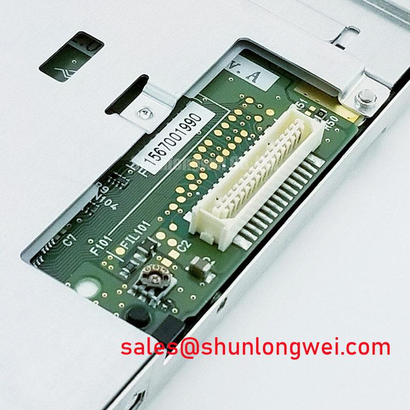
Before connecting a controller, compare the panel connector keying, pin numbering orientation, cable part number, signal labels, backlight pins, and ground arrangement. A connector with the same pitch can still have a different pin assignment. Confirm the power-on sequence, display enable behavior, reset handling, and backlight enable timing against the controller and panel requirements. If the replacement shows a white screen, split image, missing color channels, unstable startup, or intermittent synchronization, inspect the signal path and timing with the known-good equipment configuration before assigning the fault to the panel.
For differential interfaces, controlled impedance routing and short return paths are useful design considerations. A commonly used 100 ohm differential characteristic impedance is not confirmed here as an NL6448BC20-35D factory requirement. The PCB designer should follow the controller and panel interface documentation, then validate waveform quality at the receiver under the final cable length and enclosure arrangement. Oscilloscope checks should examine differential amplitude, common-mode behavior, edge quality, clock relationship, and channel-to-channel skew.
JEIDA and VESA color mapping should be treated as distinct configurations. If the mapping is incorrect, the display may show abnormal colors even when power and clock activity are present. Verify the mapping in the original panel documentation and controller configuration. Do not alter mapping straps or firmware settings based only on a similar NEC model. The linked The Ultimate Guide to Industrial TFT-LCD Technology provides broader background for reviewing panel selection, interface assumptions, and common integration errors.
Cold-start validation should include the complete sequence from input power application through stable image output. If the system operates below room temperature, measure startup behavior at the intended enclosure condition and confirm that any heater, controller delay, and backlight enable logic remain within documented limits. Pixel clock stability, cable retention, connector locking, and image integrity should be checked after thermal cycling and vibration evaluation by the equipment manufacturer. These system tests determine compatibility; the model designation alone does not establish every electrical or environmental limit.