



Content last revised on September 10, 2026
Incoming Inspection and Product Identification
Begin incoming inspection of the G121SN01 V2 by checking the TFT-LCD display surface under uniform full-screen white, black, red, green, and blue test patterns before connecting it to the host controller. This practical screen test helps reveal visible pixel defects, edge-light variation, pressure marks, horizontal noise bands, and intermittent image behaviour that can be missed during a brief boot-screen check.
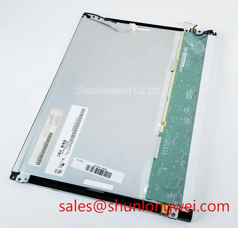
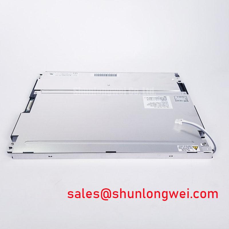
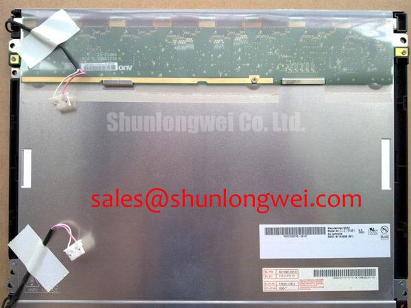
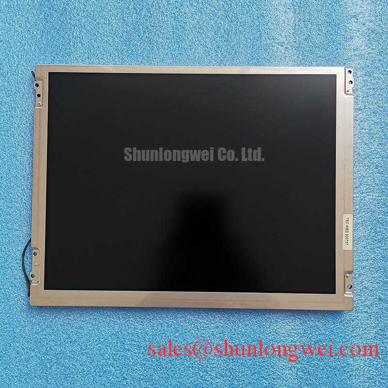
The G121SN01 V2 is identified as an AUO Industrial Grade LCD/HMI Panel supplied as a TFT-LCD Display Module. The available official factory information confirms the model identity, manufacturer, product category, and module construction category. Electrical input requirements, interface pin assignment, display resolution, optical performance, mechanical outline, operating-temperature range, and backlight configuration must be checked against the original equipment documentation or the applicable AUO panel datasheet before installation.
| Model | G121SN01 V2 |
| Manufacturer | AUO |
| Product Category | Industrial Grade LCD/HMI Panel |
| Module Type | TFT-LCD Display Module |
| Specification Status | Model and Category Verified |
Radiated Emissions Evaluation (CISPR Class A/B) and Display Backplate Grounding
A display module cannot independently be declared compliant with a complete CISPR Class A or Class B equipment-level emissions requirement. Emissions behaviour depends on the finished enclosure, power conversion stages, cable routing, grounding architecture, display controller, connected harnesses, and the final equipment test configuration. For the G121SN01 V2, EMC work should therefore begin at the system interface rather than by assigning a compliance status to the panel itself.
When a replacement display is being evaluated in equipment located near variable-frequency motor drives, inspect the cable path from the host controller to the panel before assuming that visible interference originates inside the LCD module. Horizontal bands, momentary pixel shimmer, unstable image edges, or intermittent screen corruption can be associated with common-mode noise entering through the signal cable, power harness, chassis reference, or connector shield path. Compare the affected installation against a known-good path where possible, using the same controller and a controlled cable arrangement.
Design Consideration: a conductive display backplate and shielded signal assembly are usually evaluated as part of the enclosure bonding strategy. The cable shield should have a deliberate chassis termination strategy appropriate to the equipment architecture. A 360-degree shield connection at the enclosure entry can help maintain high-frequency shielding continuity where the cable and connector system support it. Ferrite components may also be evaluated for common-mode suppression, but their material choice and placement must be verified in the finished product through conducted and radiated tests.
The supplied factory information does not establish an anti-glare finish, contrast ratio, or sunlight readability value for this exact model. Do not treat a general industrial LCD requirement such as contrast stability at high ambient illumination as an official G121SN01 V2 rating. For cab-signalling displays, passenger information terminals, or other bright-environment equipment, validate the actual installed viewing condition with the original panel documentation and a full-system optical inspection.
Clean the viewing surface with an approved non-abrasive method and inspect the front face from normal working angles. A panel can show acceptable test patterns in a dark bench environment while still presenting reflections, local brightness variation, or insufficient visual separation once it is installed behind a cover window. The panel, optical stack, touch overlay if fitted by the equipment maker, and enclosure window must be assessed as one visible assembly.
💡 Bench Tip: Disconnect power, use ESD controls, and keep the display cable perfectly level with its connector before engaging the lock because a skewed insertion can create intermittent image faults without leaving obvious external damage.
Low-Temperature Operation: Evaluating Frame Lag & Image Smearing in Outdoor Industrial Facilities
Before approving the G121SN01 V2 for a low-temperature or outdoor installation, compare the actual equipment temperature profile with the environmental limits listed in the original AUO documentation. The available verified product information does not provide an operating-temperature range, storage-temperature range, response-time specification, liquid-crystal transition data, perimeter sealing information, or LED-backlight lifetime rating. Those values must not be inferred from the Industrial Grade LCD/HMI Panel classification alone.
At reduced temperatures, liquid-crystal displays can show slower visual transitions, image persistence, and altered grayscale behaviour. These effects are system observations rather than a basis for assigning a specific low-temperature capability to this model without its official datasheet. During evaluation, allow the display, host controller, and enclosure to stabilise at the intended temperature, then cycle through grayscale ramps, moving text, menu transitions, solid-colour screens, and the actual application graphics. Compare the result with a known-good display operating in the same condition.
If smearing is visible after cold exposure, inspect several variables before replacing the panel. Confirm that the controller is supplying the intended image timing, that the display cable is fully seated, and that the enclosure is not applying uneven mechanical load to the front surface. Review whether the image behaviour changes after temperature recovery. This separates a temperature-related optical response observation from a possible controller, cable, connector, or installation issue.
Backlight brightness should be assessed through repeatable observation rather than an assumed service-life figure. The factory information supplied for the G121SN01 V2 does not specify a brightness-retention curve, a half-brightness lifetime, or constant-current driver requirements. Where the original machine includes backlight control or dimming circuitry, verify its output and control state using the equipment service information. Do not substitute a generic LED lifetime value for an official module specification.
Design Consideration: thermal cycling evaluation should include the display mounting points, bezel clearance, cable bend region, connector retention, and any equipment-level gasket. The purpose is to identify whether differential expansion or enclosure movement creates mechanical stress that becomes visible as intermittent display operation, edge shading, or surface pressure marks. The exact test limits, dwell periods, and acceptance criteria must be set by the system owner and applicable equipment requirements.
For long-term maintenance planning, review The Ultimate Guide to Industrial TFT LCD Technology alongside the original panel documentation. It provides useful context for distinguishing panel-level attributes from enclosure, controller, backlight-driver, and application-level conditions that affect the final display result.
Flush-Mount Open-Frame Bezel Integration & Perimeter Gasket Shock Isolation
Mechanical fit should be verified from the original G121SN01 V2 mechanical drawing, not from the appearance of another LCD panel with a similar screen format. The confirmed factory information identifies this item as a TFT-LCD display module but does not provide the active area, outside dimensions, bezel geometry, mounting-hole locations, thickness, or fastening details. A replacement decision should therefore include a drawing-to-chassis comparison before the display is mounted.
Place the module on a protected flat bench and inspect the bezel perimeter, rear structure, connector area, and mounting features under angled light. Look for evidence that the existing enclosure has imposed point loading or uneven compression. Dark regions, local bright spots, or non-uniform areas visible on a black or mid-gray pattern can be related to many conditions, including panel handling, mounting stress, cover-window pressure, or pre-existing display variation. The observation should be recorded before and after installation so that the mounting process can be evaluated objectively.
Engineering Recommendation: tighten display fasteners gradually in a cross-pattern sequence when the equipment structure uses multiple mounting points. The purpose is to distribute load rather than pull one side of the module into position first. The final fastening method, torque, gasket thickness, compression target, and isolation hardware must be determined by the machine manufacturer’s mechanical design and the panel drawing. Do not apply a generic torque value to this model without confirming its mounting specification.
A perimeter gasket can be useful where an enclosure requires vibration isolation, dust management, or controlled spacing between a cover window and display face. Its material, compression behaviour, chemical compatibility, and environmental suitability are properties of the finished equipment assembly. They are not confirmed characteristics of the G121SN01 V2 itself. Confirm that the gasket does not transfer a continuous force into the visible panel area after the enclosure screws are secured.
The interface type and differential-pair requirements for the G121SN01 V2 are not stated in the verified information provided here. The system integrator should verify the required interface, connector pinout, signal mapping, supply voltage, and cable specification from the original panel documentation. If the documented interface uses differential signalling, controlled impedance, pair symmetry, return-path continuity, and cable shielding remain Design Considerations for preserving signal integrity in electrically noisy equipment.
For a separate hardware comparison during service evaluation, G104VN01 V1 can be reviewed as a verified display-module reference. It should not be assumed to be a drop-in replacement for the G121SN01 V2. Mechanical dimensions, electrical requirements, interface mapping, optical characteristics, and host-controller compatibility all require independent confirmation.
Logic Supply Voltage Sequencing and Driver IC Latch-Up Risk Evaluation
Do not select a 3.3 V or 5.0 V logic supply for the G121SN01 V2 based on common LCD conventions. The available official product information does not identify the required supply voltage, power sequence, rise-time limits, connector allocation, interface mapping, or control-signal state requirements. The system integrator should verify the required supply voltage from the original panel documentation before connecting a controller, bench supply, or replacement cable.
Power sequencing should be treated as a host-system verification task. A display controller, logic rail, backlight supply, enable signal, and data path can interact differently depending on the original panel architecture. Applying voltage to an uncertain pin assignment or activating a backlight circuit before the correct logic condition is established can create an inconclusive fault condition and may damage connected equipment. Confirm connector orientation, pin numbering, ground references, and measured rail behaviour against the documented panel interface.
During bench troubleshooting, use the original controller where practical and observe startup behaviour with a known-good signal source. Check whether the screen remains blank, displays unstable content, shows split regions, or changes after cable movement. Such behaviour may indicate an interface, power, timing, connector, or panel-related issue; it should not be assigned to one cause without measurement. An oscilloscope comparison with a known-good signal path can help determine whether the source timing and differential waveform remain consistent at the display connector.
JEIDA and VESA mapping are controller and panel interface conventions, not interchangeable assumptions. If a host controller supports more than one mapping mode, confirm the mode required by the original display documentation. Incorrect mapping can produce abnormal colour order, missing colour content, divided images, or other output anomalies even when the mechanical connection appears correct.
When evaluating the G121SN01 V2 for railway passenger information systems or cab-signalling display maintenance, treat the original equipment drawing set as the authority for interface compatibility. Confirm the panel label, mating cable, controller output standard, electrical rails, sequence requirements, mechanical retention, and observed screen performance before returning the equipment to service.