Content last revised on October 14, 2026
G121ACE-LH1 Integration and Viewing-Angle Checks for Multi-Angle Consoles
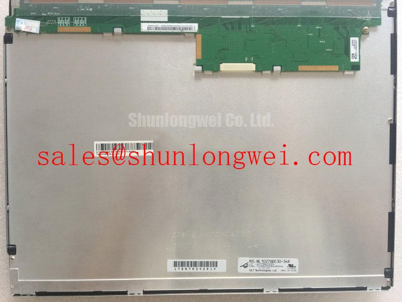
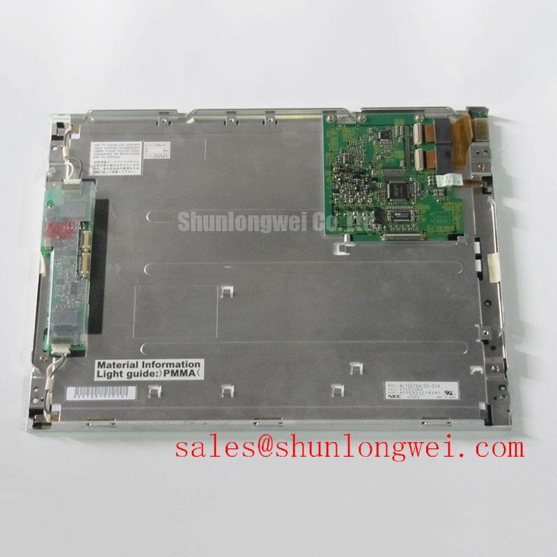
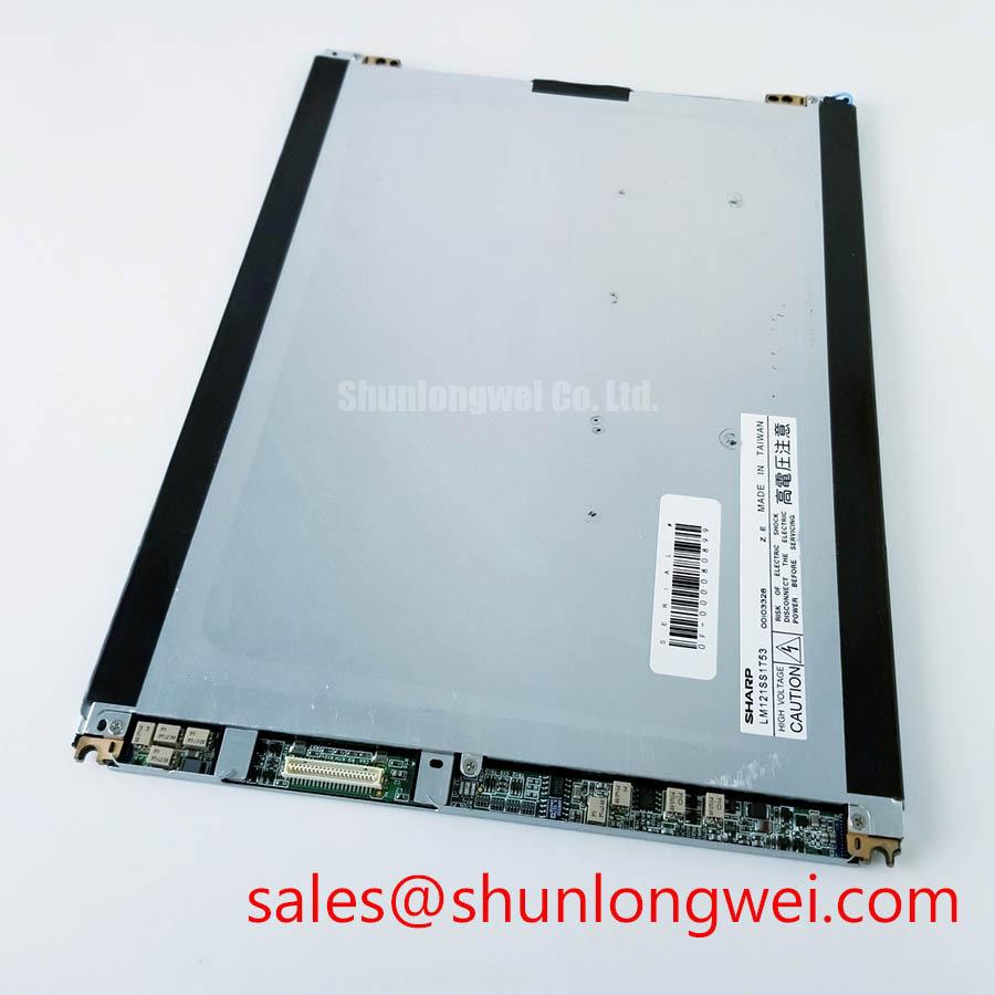
Before installing G121ACE-LH1, isolate the display assembly, inspect the TFT-LCD module and connector area under controlled lighting, and verify the original equipment documentation for supply voltage, signal mapping, backlight type, and mounting dimensions. The available factory information identifies this unit as an AUO Industrial Grade LCD/HMI Panel in a TFT-LCD Display Module format, with its specification status listed as Official Factory Spec Verified. Interface and electrical values that are not stated in the supplied factory data must be confirmed against the original panel documentation before power is applied.
For overseas repair teams, this distinction is important. A panel replacement can fit mechanically while still failing at the electrical interface, backlight driver, timing controller, or cable level. Treat G121ACE-LH1 as a specific AUO display module requiring system-level compatibility checks rather than assuming that a similar-looking LCD will share the same connector assignment or operating conditions.
The viewing-angle values shown in the requested integration brief should be treated as evaluation targets unless they are confirmed by the original AUO datasheet for this exact part number. The supplied factory information confirms the product category and module construction, but does not provide a verified viewing-angle table, contrast ratio, surface treatment, response time, or luminance value. Engineers evaluating the G121ACE-LH1 for a multi-angle console should therefore compare the actual panel documentation with the viewing geometry of the host equipment.
In a surgical navigation display or ultrasound diagnostic terminal, operators may view the screen from the side while standing beside the console. A panel with grayscale inversion or color shift can make small measurement labels and low-contrast image features harder to interpret. During assessment, display a known test pattern containing neutral gray steps, fine text, and dark image areas. Observe the image from the intended operator positions rather than judging the panel only from the centerline.
Surface reflection is a separate issue from viewing angle. If the equipment operates beneath strong examination lighting, inspect the panel with the enclosure, front window, and surrounding bezel installed. An anti-glare surface may reduce mirror-like reflections, but it can also alter perceived sharpness and black-level detail. The G121ACE-LH1 factory data supplied for this page does not confirm an AG etch, optical bonding construction, or a specific contrast ratio. These characteristics should be verified from the original AUO documentation or measured on an approved sample.
Backlight control also requires system verification. The requested engineering brief references a PWM range of 200 Hz to 1 kHz, but this is not a confirmed G121ACE-LH1 factory parameter. If the host uses PWM dimming, the integrator should verify the backlight driver interface, modulation frequency, duty-cycle behavior, and camera interaction. A practical bench check uses a photodiode or suitable flicker measurement instrument while the panel displays text, grayscale ramps, and moving diagnostic imagery. Audible noise should be checked separately at the driver and power-conversion stages because visual modulation and acoustic vibration are different failure paths.
For replacement planning, compare the original panel’s active area, outline, connector location, mounting holes, cable exit direction, and optical stack before approving a substitute. The G104VN01 V1 may be reviewed as a separate display candidate, but it should not be treated as a drop-in replacement until resolution, interface, mechanical envelope, backlight requirements, and firmware timing have been checked against the host display controller.
Grounding and Radiated Emissions in Display Assemblies
G121ACE-LH1 is an LCD display module, not an independently certified CISPR Class A or Class B system. Radiated and conducted emissions depend on the complete assembly, including the controller board, cable harness, backlight circuit, enclosure, power supply, grounding strategy, and nearby switching equipment. A display module page should not be used as evidence of whole-system EMC compliance.
When a screen is installed near a variable-frequency motor drive, first separate image faults from power and signal faults. Record the symptom with the motor drive disabled, then repeat the observation with the drive operating through its normal speed range. Pixel jitter, intermittent lines, or horizontal noise bands may involve common-mode coupling, cable routing, connector contact, controller timing, or power supply disturbance. Verify the signal path with the known-good cable and controller where available, and use an oscilloscope only with suitable probes and grounding methods.
A shielded LVDS or FFC cable should be routed according to the host equipment design, keeping high-current switching conductors physically separated from sensitive display wiring where practical. The exact cable construction, shield termination, connector assignment, and chassis bonding method are not confirmed by the supplied G121ACE-LH1 factory data. Designers should verify whether the original assembly uses a full shield, conductive frame contact, drain connection, or a board-level reference path before changing the harness.
Star grounding can be considered as an enclosure-level strategy when multiple noisy return paths are creating common-mode current. It is not a guaranteed remedy for every display artifact. The system engineer should evaluate the return-current path, bonding points, cable shield termination, and power supply reference while monitoring both the display image and emissions. Ferrite components may be considered where testing identifies a conducted or radiated noise path, but their impedance behavior must be selected for the actual cable, frequency range, current, and installation geometry.
Claims about stable optical contrast under direct sunlight, including values above 500:1 at 50,000 lux, require a verified optical specification or controlled measurement. They should not be assigned to this model from the product category alone. For a high-precision medical display evaluation, test the complete front assembly under representative ambient light and confirm that the displayed image remains readable after the front cover, bezel, and cleaning procedure are included.
Field Alert: Disconnect system power and allow the host supply to discharge before removing or inserting the display cable, because an energized connector can expose signal and power contacts to transient stress.
Acoustic Buzz and EMI in PWM-Controlled Backlight Systems
The supplied information does not confirm whether the G121ACE-LH1 uses a CCFL backlight, an LED backlight, a particular inverter, or a dedicated constant-current driver. Do not select a replacement backlight circuit from appearance alone. The system integrator should verify the original panel documentation and the installed controller before connecting a driver.
When a repaired display produces a high-pitched sound, inspect the complete power path rather than assigning the noise to the LCD glass. Possible contributors include the backlight converter, magnetic components, capacitors, PWM control, mechanical mounting, or an enclosure panel that amplifies vibration. Change only one test condition at a time and compare the sound with the backlight enabled, disabled, and operated at the host system’s normal brightness settings.
The requested brief refers to high-voltage CCFL ignition in the range of 1500 to 1650 Vrms, constant-current LED operation, 1000:1 PWM dimming, and a 50,000-hour half-life target. These values are not confirmed factory parameters for G121ACE-LH1 in the information supplied here. They must not be presented as specifications of this AUO module. A repair engineer should identify the installed backlight technology, measure the driver output only with equipment rated for that circuit, and verify any replacement driver’s enable, dimming, protection, and feedback requirements.
For text-heavy HMI screens, flicker evaluation should include low brightness, medium brightness, and rapid brightness transitions. If PWM is used, the host designer should verify modulation frequency and duty-cycle linearity against the display’s actual optical response. A camera-based check may reveal rolling bands that are not obvious to the naked eye, while a photometric instrument can provide a more repeatable comparison. No specific flicker performance should be assumed for G121ACE-LH1 without a panel-level measurement or manufacturer data.
Long-duration static images also deserve a controlled evaluation. Fixed icons, status bars, and measurement scales can remain in the same location for extended periods, so the host software team may consider modest layout movement, screen blanking, or brightness management where the application permits. These are system design considerations, not confirmed anti-burn-in features of the panel. The supplied data does not establish a panel half-life, image-retention rating, or medical-use certification.
A separate display such as LMS700KF01-001 can be evaluated where the equipment architecture calls for another display. It should not be treated as a substitute for G121ACE-LH1 without confirming the interface, mechanical dimensions, backlight requirements, and controller compatibility.
Data Mapping Alignment and Signal Integrity Checks
Split-screen images, incorrect colors, missing gray levels, and unstable synchronization require an interface comparison before any panel is condemned. Confirm the host controller output standard, pixel format, lane arrangement, bit mapping, connector orientation, and cable pinout against the original AUO documentation. The supplied factory data does not confirm whether G121ACE-LH1 uses VESA mapping, JEIDA mapping, a particular LVDS lane count, or a defined logic supply voltage.
The integration brief references logic supplies of 3.3 V or 5.0 V and a power-on rise-time window of 0.5 ms to 10 ms. Those values are not verified specifications for this model. The system integrator should verify the required supply voltage and power sequence from the original panel documentation. Apply power only after confirming ground, logic supply, enable, timing, and backlight connections. A mismatch can produce a blank screen, white screen, residual image, or an apparently defective panel even when the display module itself is functional.
Power sequencing should be checked with the host controller and backlight driver connected as they will be used in service. Monitor the relevant rails and control signals during startup and shutdown, then compare the waveform with the timing requirements of the confirmed panel interface. If a white screen appears, inspect the logic supply, reset or enable state, cable seating, and data mapping before changing the display module. If a residual image remains after shutdown, check whether the controller or backlight supply is discharging as intended and whether the panel is receiving an unintended signal state.
Differential routing should preserve the impedance and reference conditions required by the confirmed interface design. The requested brief mentions 100-ohm differential routing, but this is a system-level routing consideration rather than a verified G121ACE-LH1 specification. Keep paired conductors controlled through the connector and cable transition, avoid unnecessary stubs, and verify the complete path with the board designer. Even and odd channel errors can result from swapped pairs, reversed polarity, incorrect bit mapping, poor contact pressure, or a controller configured for a different panel family.
Flexible cable handling is equally important during emergency replacement. Support the cable close to the connector, avoid folding directly over the contact area, and use the original bend direction where possible. The factory information supplied here does not specify a flex-life rating or connector insertion cycle count. Inspect the latch, stiffener, exposed contacts, and cable seating whenever the symptom changes after enclosure movement. For a long-life installation, the mechanical team should control cable strain and confirm that the bezel does not press on the connector or FPC.
For broader evaluation of TFT-LCD interfaces, optical behavior, selection criteria, and common integration issues, consult The Ultimate Guide to Industrial TFT-LCD Technology. Final acceptance of G121ACE-LH1 should remain tied to the original AUO documentation, the host controller configuration, measured startup and shutdown behavior, and the complete display assembly used in the target equipment.