

Content last revised on October 21, 2026
Backlight Driver Selection, PWM Dimming & Flicker Suppression
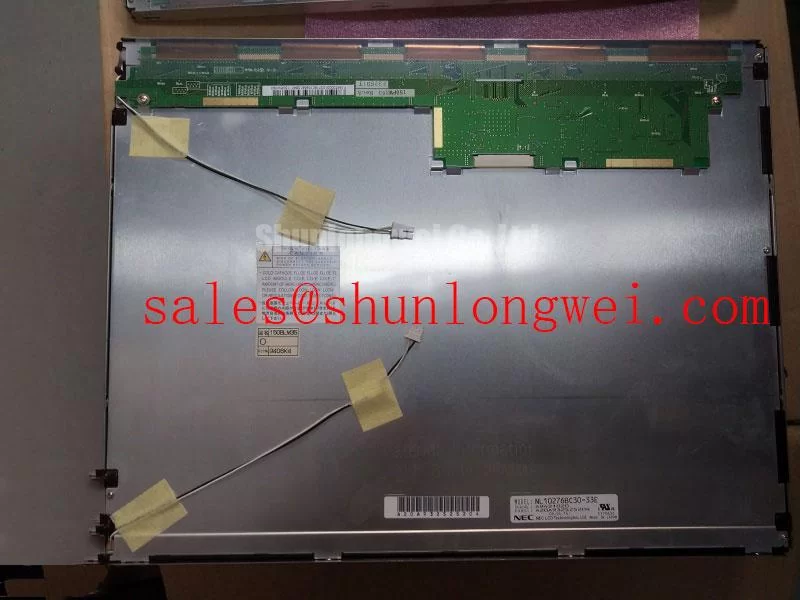
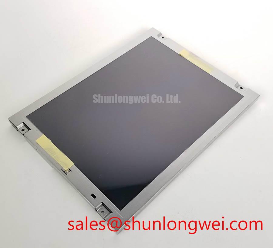
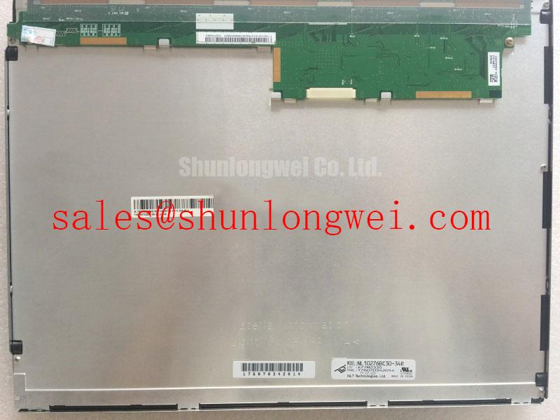
When a railway passenger information display or cab signalling screen shows uneven illumination, first separate the panel assembly from the cabinet’s backlight driver. The NL10276BC30-34R is identified as a NEC TFT-LCD active matrix color display module; the original equipment documentation must define the actual backlight architecture, drive current, dimming input, and connector arrangement before a replacement driver is selected.
Older equipment may use a high-voltage CCFL inverter, while a later retrofit may use an LED constant-current driver. These are different electrical systems and cannot be treated as interchangeable by appearance alone. A CCFL system should be checked for ignition behavior, inverter output stability, and abnormal acoustic noise. An LED system should be assessed through its constant-current output, enable signal, PWM response, and thermal distribution across the light source.
The often quoted 1000:1 PWM dimming capability and 50,000-hour half-brightness reference belong to the driver and backlight system evaluation, not automatically to this NEC display module. Design engineers should compare the replacement panel’s optical response with the existing controller at minimum, nominal, and maximum brightness settings. Observe whether the luminance changes smoothly or whether the screen exhibits visible modulation, uneven zones, or audible interaction with the cabinet structure.
For long service intervals, inspect the airflow path behind the display and check whether the sealing gasket has compressed, shifted, or accumulated dust. Maintenance Note: Power down the equipment before disconnecting the display cable, and inspect the gasket whenever the front bezel is removed.
Flashlight Dark-Shadow Optical Diagnostic to Isolate Logic vs. Backlight Failure Modes
A dark screen should be tested with a controlled image before the panel is condemned. Apply primary red, green, blue, white, and black patterns from the host display controller, then view the screen at an oblique angle while directing a flashlight across the surface. If image detail becomes visible under the beam, the timing controller and pixel matrix may still be operating while the backlight path requires investigation.
This observation does not establish a single fault location. Compare the result with the panel’s power state, video activity, dimming command, and backlight enable behavior. A completely uniform dark field, intermittent image regions, vertical artifacts, or fixed line defects require different checks. A line that remains attached to the same glass position points the investigation toward the panel assembly or its bonded driver region, while an artifact that follows the signal path may involve the controller, cable, or source timing.
Use the same test image with the original display and the replacement unit, keeping the cabinet brightness command unchanged. This reduces confusion caused by software dimming or a misconfigured host output. Where the original panel documentation identifies a specific T-CON sequence or gamma reference, compare the gray-scale steps rather than relying only on a white screen. Poor gamma tracking can make a backlight problem appear worse than it is.
For field material planning, maintenance teams may also compare the NL8060BC31-42 as a separate same-class display option, subject to mechanical dimensions, optical characteristics, interface mapping, and controller compatibility.
Radiated-Emissions Assessment via Backplate Multi-Point Star Grounding
When pixel jitter or horizontal noise bands appear near variable-frequency motor drives, start with the complete display wiring route rather than the LCD glass alone. Route the video cable away from switching power conductors, maintain a continuous shield reference where the equipment design supports it, and examine whether the shield termination is interrupted by painted brackets, loose fasteners, or a poorly bonded bezel.
A multi-point grounding arrangement can reduce unwanted common-mode voltage when it is compatible with the cabinet’s protective earth and signal-reference architecture. It must be validated at system level because a display module does not independently carry a CISPR Class A or Class B equipment certification. Ferrite components, cable shields, and grounding points should be selected after measuring the disturbance across the operating speed range of the nearby drive.
For railway cab and passenger information installations, sunlight and viewing angle can expose optical weaknesses that are not obvious on a workshop bench. Check contrast, reflections, and gray-scale visibility under the actual enclosure window and ambient illumination. The frequently cited values of greater than 500:1 contrast at 50,000 lux and anti-glare performance are system evaluation targets unless they are explicitly stated in the panel’s original specification. Do not assign those values to the NL10276BC30-34R without matching documentation.
For broader industrial display context, consult Tianma Industrial TFT Display Solutions. The cited page is useful for industry context, but equipment compliance remains dependent on the finished display assembly, enclosure, cable routing, and host electronics.
20-Pin/30-Pin Differential LVDS Timing, Pixel Clock & Skew Compensation
Before connecting the NL10276BC30-34R, identify the exact connector pinout and signal convention from the original panel documentation and the host controller schematic. Do not assume that a visually similar connector uses the same LVDS lane order, supply assignment, backlight control, or JEIDA and VESA mapping. A mismatch can produce split-screen images, swapped color channels, unstable synchronization, or no image.
Check the controller’s power-on sequence with an oscilloscope while observing the panel enable and video activity signals. The supplied engineering brief references logic supply evaluation at 3.3 V or 5.0 V and a rise-time window of 0.5 ms to 10 ms, but these values must be matched to the confirmed panel documentation and controller design rather than treated as universal ratings for this model.
Differential routing should preserve the intended characteristic impedance and keep paired conductors closely coupled through transitions. The commonly used 100 ohm differential target is a board and cable design consideration, not a standalone certification of this display. Verify clock quality, lane alignment, and skew under the installed cable length and cabinet noise conditions. A known-good image pattern is more useful than a static color screen when checking intermittent timing errors.
PWM brightness control also belongs to the combined controller and backlight system. The referenced 200 Hz to 1 kHz range may be used as a bench evaluation window only when permitted by the selected driver and display documentation. Check duty-cycle linearity, visible flicker, and acoustic behavior at low brightness. For broader background on TFT architecture, interface selection, and common integration misunderstandings, consult The Ultimate Guide to Industrial TFT Display Technology.