



Content last revised on September 10, 2026
NEC NL8060BC31-42 Verification and Integration Considerations
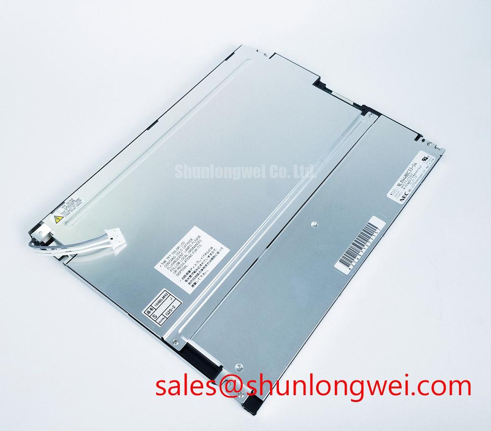
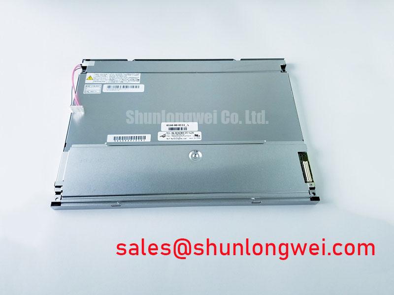
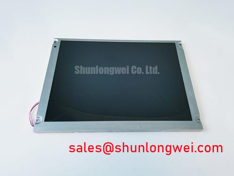
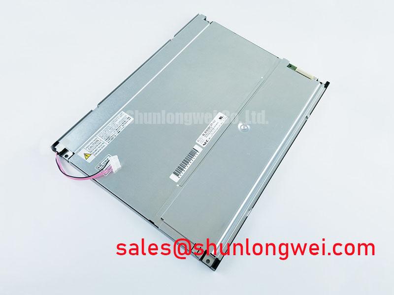
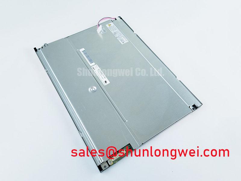
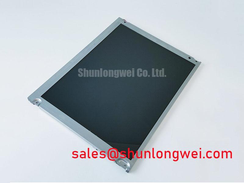
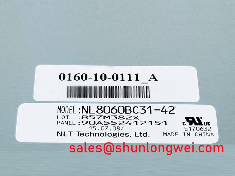
Before installation, inspect the NL8060BC31-42 module perimeter, display surface, connector area, and mounting interface under neutral lighting, then compare the unit marking and original equipment documentation before applying power. This NEC unit is identified in the available product information as an Industrial Grade LCD/HMI Panel in a TFT-LCD Display Module enclosure.
The available factory information confirms the product category and module form, but it does not establish the display resolution, active area, interface type, panel supply, backlight architecture, brightness, viewing angle, operating temperature range, or mechanical dimensions. These characteristics must be verified from the original panel documentation and the host equipment configuration before an integration decision is made. For repair work, retaining the original harness routing, connector orientation, bezel geometry, and power sequencing evidence is often more useful than relying on visual similarity between panels.
| Item | Available Information |
|---|---|
| Model | NL8060BC31-42 |
| Manufacturer | NEC |
| Product category | Industrial Grade LCD/HMI Panel |
| Module form | TFT-LCD Display Module |
| Documentation status | Product category and module form are identified, while detailed electrical, optical, mechanical, and environmental specifications require confirmation from the original documentation. |
| Unverified integration items | Supply rails, signal interface, timing, backlight requirements, dimensions, mounting details, optical ratings, and environmental limits require confirmation from original documentation. |
In equipment such as an explosion-protected operator station or field monitoring terminal, the display module remains only one part of the complete protected assembly. Enclosure sealing, cable glands, display window construction, system grounding, power conversion, and area classification are determined at system level. The module itself should not be represented as carrying a complete equipment safety or electromagnetic compliance approval.
Luminance Output Control and L70/B50 Lifetime Concepts
Start luminance troubleshooting by separating image generation from illumination. With the operator station safely isolated according to the equipment procedure, observe whether a faint image can be seen under controlled external illumination when the screen appears dark. A visible image without normal screen illumination can indicate that the signal path is active while the illumination path requires further investigation. A fully blank image, unstable picture, or recurring white screen requires review of the host-side power sequence, connector engagement, and the original signal source rather than an assumption about the display module alone.
The available official information does not confirm that the NL8060BC31-42 uses an LED backlight, nor does it publish an L70 or B50 lifetime value. Therefore, no LED lifetime figure, constant-current requirement, aluminium rail dimension, thermal limit, or optical material behaviour should be assigned to this exact model without the original NEC documentation. References to L70 and B50 are useful maintenance concepts only when a panel’s documented backlight technology and test conditions are known.
Design Consideration: narrow bezel regions and enclosed operator terminals can retain heat around the display assembly. When the original panel documentation identifies a backlight system with thermal constraints, the enclosure designer should provide an appropriate heat path and avoid obstructing airflow around the display cavity. The final arrangement must be validated in the completed terminal under its own duty cycle, ambient conditions, protective window construction, and internal power dissipation.
Optical bonding, perimeter gaskets, and protective windows are also system-level choices. They can reduce dust entry and help control condensation pathways when correctly specified for an enclosure, but they do not replace a review of the panel’s permitted mechanical loading. If a bonded front stack is part of the existing station, inspect for edge separation, trapped contamination, seal discontinuity, and pressure marks before attributing luminance variation to the LCD module.
Where a host controller uses differential video signalling, the system integrator should verify the actual interface from the original panel documentation before discussing trace impedance, pair skew, clock quality, or transmitter configuration. Impedance-controlled differential routing and an interface-appropriate skew budget are Design Considerations for high-speed differential display links, not published specifications of the NL8060BC31-42. In high-noise factory cabinets, waveform integrity should be checked against the known-good signal path and the controller timing requirements.
For maintenance planning, document the display brightness setting, terminal internal temperature trend, ventilation condition, and operating hours available from the equipment controller. This creates a practical baseline for later comparison without inventing a service-life prediction for the panel.
Evaluating Localized Optical and Mounting Stress on Dark Screen Fields
Dark screen fields are particularly useful for detecting uneven bezel pressure, light leakage, edge shading, and localized mura. Run the display with a controlled dark test image only after confirming the original electrical connection and intended power-up sequence. View the screen from the normal service position and then at moderate off-axis angles. Changes in shading with angle can help distinguish a surface reflection, enclosure pressure effect, protective-window contamination, or image-path issue, although they do not identify one exclusive root cause.
The official information supplied for the NL8060BC31-42 does not define a light guide plate, its material, allowable compression, bezel envelope tolerance, fastener count, or mounting torque. It is therefore not appropriate to state that this NEC model contains a particular optical structure or to assign a factory torque value to it. The original drawing and host chassis design remain the controlling references for mounting holes, support lands, clamp zones, and permitted panel deflection.
Design Consideration: when a display is clamped within a metal operator-station bezel, use a balanced tightening sequence so mounting stress is distributed rather than concentrated at one corner. Use only the torque specified by the applicable mechanical drawing or fastener and chassis design. The correct torque is determined by the specified screw, thread engagement, chassis material, washer arrangement, gasket stack, and approved mechanical drawing.
⚠️ Maintenance Note: Recheck bezel fasteners, perimeter gaskets, and cabinet ventilation during scheduled service because uneven clamping or deteriorated sealing can create visible screen non-uniformity and condensation risk.
Do not force a panel into a chassis opening that differs from the existing module geometry. A display that seats only after bending, twisting, or local shimming should be removed and the mechanical interface reviewed. Flexing can place load on the glass edge, bonded connections, rear housing, or cable exit area. In humid industrial environments, moisture found behind a window or around a gasket should prompt inspection of the enclosure sealing path and temperature cycling conditions rather than a presumption that the panel itself has failed.
For a technical comparison during a replacement assessment, the NL10276BC16-06 can be reviewed alongside the original equipment documentation. It should not be treated as a direct replacement unless the system integrator confirms mechanical fit, active-area alignment, connector assignment, electrical requirements, timing, optical performance, and enclosure compatibility.
Backlight Type, Driver Requirements, PWM Dimming, and Flicker Suppression
The phrases WLED, constant-current drive, high-ratio PWM dimming, CCFL ignition voltage, acoustic noise, and backlight life describe different backlight and driver questions. They are not verified attributes of the NL8060BC31-42 from the supplied official information. The panel documentation and the original operator-station circuit must establish the installed backlight type and the required driving method before any driver board, inverter, dimming command, or illumination supply is evaluated.
No statement should assign a CCFL cold-ignition range, a PWM dimming ratio, or any lifetime figure to this model. Such values depend on a specific backlight design, electrical operating point, ambient condition, brightness setting, and test method. They must not be transferred from a different NEC display module or from general display practice.
Engineering Recommendation: inspect the existing display harness and host board for evidence of a dedicated backlight control connection, power converter, or inverter stage, then compare each connection with the original panel documentation. If the host design employs pulse-width modulation, verify the control polarity, valid frequency range, enable logic, and timing requirements from the appropriate source documents. A scope measurement at the known-good host output can help identify intermittent control activity, noise coupling, or abnormal timing without assigning a single cause to a flicker symptom.
For industrial HMI screens that hold static process graphics for long periods, operational practices matter as much as the panel selection. Where the application software allows it, controlled screen dimming, display-off periods, and periodic refresh of static high-contrast elements can be assessed by the system owner. These are application-level measures and do not establish a guaranteed resistance to image retention for the NL8060BC31-42.
Power sequencing also requires panel-specific confirmation. A white screen at startup, residual image during shutdown, or intermittent recovery after a cabinet restart can involve the host supply ramp, signal-valid timing, display enable control, cable seating, or the module itself. The system integrator should verify the required supply voltage from the original panel documentation and compare observed startup behaviour with the host equipment’s intended sequence. Avoid connecting or disconnecting the display cable while the terminal is energized.
Where another NEC display solution is being evaluated as part of a wider service review, the NL10276BC30-24D provides a related reference point for documentation comparison. Its presence in a parts review does not establish electrical, optical, mechanical, or backlight-driver interchangeability with the NL8060BC31-42.
Incoming Benchtop Inspection: Display Bond and Connector Integrity
Incoming inspection should begin with a clean, ESD-controlled bench and the original mating hardware where available. Examine the display face for scratches, edge chips, pressure marks, trapped debris, and signs of enclosure contact. Inspect the rear module surfaces and connector region without prying, scraping, or pressing on bonded areas. The supplied factory information does not identify the internal connection technology of this exact model, so COG, TAB, and anisotropic conductive film construction must not be asserted as confirmed product features.
A practical three-stage colour evaluation can be performed only after the correct electrical interface and sequence have been verified. Present a uniform red field, then a uniform green field, then a uniform blue field from a verified signal source. Observe for fixed lines, missing sections, colour imbalance, intermittent image regions, and changes produced by gentle cable movement at the connector rather than by pressure on the display glass. Findings should be recorded as observations. A line defect, uneven illumination, or colour anomaly can have several possible origins across the source board, cable, connector, timing path, panel electronics, and optical assembly.
A controlled flashlight observation can also help differentiate visible image content from illumination loss. Hold the light at an oblique angle, approximately 45 degrees to the screen surface, without touching the polarizer or protective window. If underlying content becomes visible only under external light, continue diagnosis through the system’s illumination path and documented panel requirements. If no content appears, review the source and timing path as well. This method is a screening practice, not proof of a particular internal fracture or bond failure.
In installations exposed to vibration, service technicians should check that the flexible cable has adequate strain relief, the connector latch is fully engaged, and the cable route does not place repeated bending load at the connector exit. FPC bend-life limits, latch force, and permitted cable geometry require source documentation; they should not be inferred from appearance. Likewise, confirmation of TTL, LVDS, or another signalling format requires the original panel pinout and controller schematic. Clock jitter margins and data hold times must be evaluated against that confirmed interface across the actual operating temperature window.
For a broader reference on display architecture, interface evaluation, common installation questions, and structured fault isolation, consult The Ultimate Guide to Industrial TFT LCD Technology. Use it together with the original equipment documentation when assessing the NEC NL8060BC31-42 in a sealed industrial HMI or monitoring terminal.